 |
|||
|
|
|||
|
Page Title:
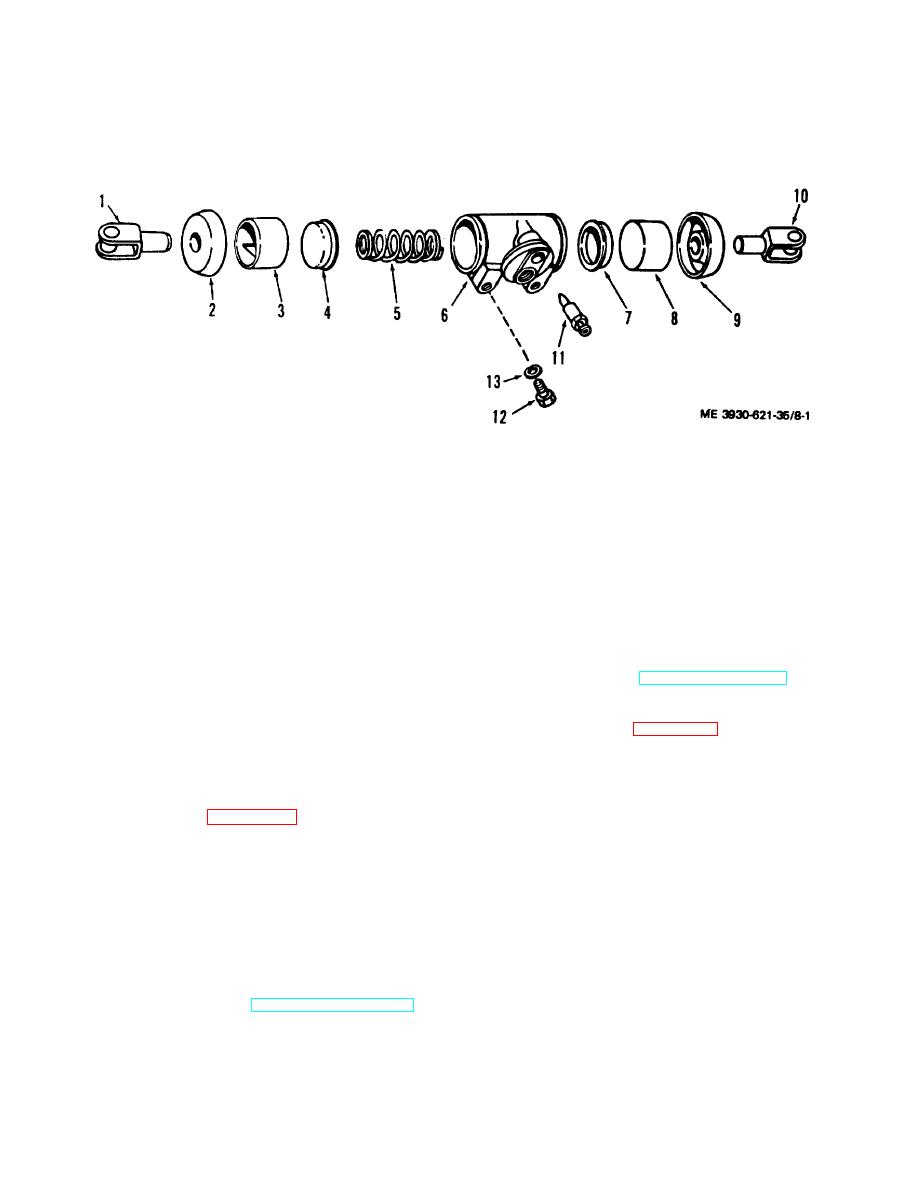
Figure 8-1. Brake wheel cylinder exploded view. |
|
||
| ||||||||||
|
|
 TM 10-3930-621-34
(3) Push out pistons (3 and 8), piston cups (4internal
internal parts.
and 7), and spring (5) from cylinder body (6). Low
(4) Remove bleeder (11).
pressure air at fluid inlet can also be used to remove
Figure 8-1. Brake wheel cylinder exploded view.
1. Connecting link
8. Piston
2. Boot
9. Boot
3. Piston
10. Connecting Link
4. Piston cup
11. Bleeder
5. Spring
12. Capscrew
6. Cylinder body
13. Lockwasher
7. Piston cup
d. Cleaning and Inspection.
8-5. Master Cylinder
(1) Clean all parts thoroughly and keep them
a. Description. The brake master cylinder and fluid
clean until unit is ready for assembly. Use lint free cloth
reservoir are combined in one casting, and are joined by
for cleaning.
intake and by-pass ports in the cylinder wall. Internal
Caution: Wash parts thoroughly it denatured
parts are removable through the push rod end.
b. Removal. Refer to TM 10-3930-621-12 for removal
alcohol or clean brake fluid Never use gasoline,
procedures.
kerosene, paint thinner or other mineral base
c. Disassembly.
solvents as they will damage rubber components.
(1) Refer to figure 8-2 and disassemble as
(2) Thoroughly inspect all parts for wear,
follows:
corrosion or other conditions which might impair cylinder
(2) Secure cylinder in vise, using care not to
action.
distort or crack casting.
(3) Replace defective parts as authorized. e.
(3) Remove boot (12) and piston rod (11).
Assembly).
(4) Holding piston assembly (15) in cylinder,
(1) Refer to figure 8-1 and assemble as
gently pry off lockwire (13).
follows:
Caution: When lockwire removed, continue
(2) Lubricate all parts and cylinder walls with
holding piston in place or entire assembly will spring
clean brake fluid.
out.
(3) Insert spring (5) and piston cups (4 and 7) in
cylinder body.
(5) Slowly relax hold on piston and carefully
(4) Insert each piston (3 and 8) in its respective
remove stop plate (14), piston assembly (15),
end. Never attempt to push piston through length of
rubber piston cup (10), retainer (9), spring (8), and
cylinder.
check valve (7).
(5) Install boots (2 and 9), being sure they are
(6) Remove bolt (1), gaskets (2), and fitting (3).
properly located in grooves provided.
(7) Remove filler plug (4) and gasket (5).
f.
Installation. Refer to TM 10-3930-621-12 for
installation procedures.
8-2
|
|
Privacy Statement - Press Release - Copyright Information. - Contact Us |
