 |
|||
|
|
|||
|
Page Title:
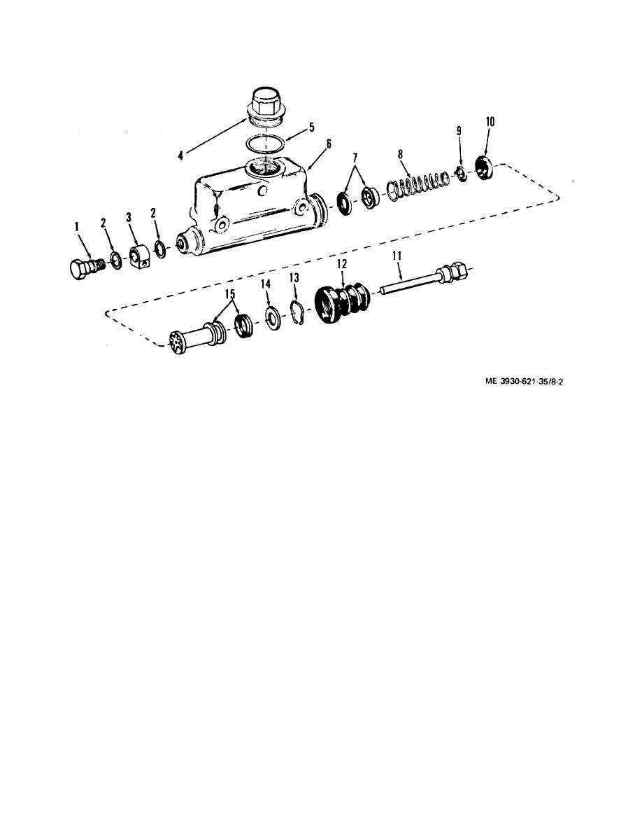
Figure 8-2. Master brake cylinder exploded view |
|
||
| ||||||||||
|
|
 TM 10-3930-621-34
Figure 8-2. Master brake cylinder exploded view
1.
Outlet bolt
9. Retainer
2.
Gasket
10. Piston cup
3.
Fitting
11. Piston rod
4.
Plug
12. Boot
5.
Gasket
13. Lockwire
6.
Cylinder and tank
14. Stop plate
7.
Check valve
15. Piston assembly
8.
Spring
d. Cleaning and Inspection.
(3) Make sure intake and by-pass ports are
(1) Clean all parts with denatured alcohol or
open. By-pass ports may be probed with soft iron wire.
brake fluid, and keep clean in all following operations.
(4) If it is necessary to resurface the cylinder wall, use
the following procedure:
Warning: Dirty parts or internal rubber
(a) Coat walls of cylinder bore with hydraulic brake
parts which become swollen, tacky, and otherwise
fluid.
deteriorated by mineral base cleaning solvents can
(b) Secure master cylinder body in a bench vise.
lead to brake failure and possible injury to the
(c) Using honing equipment, remove material from
operator.
cylinder bore in single passes.
(2) Inspect cylinder bore.
Deep blemishes
(d) After each pass is completed, remove hone and
require boring to resurface the cylinder wall. Do not bore
inspect for scratches and pitting. Remove only enough
beyond manufacturer's specifications. Pressure marks
material to recondition cylinder bore. Do not hone
may be polished out with crocus cloth.
cylinder oversize.
Caution: Do not use emery cloth or sand pa
Note. If the master cylinder has been honed
per.
oversize or greater than 1.007 of an inch it must be
replaced.
8-3
|
|
Privacy Statement - Press Release - Copyright Information. - Contact Us |
