 |
|||
|
|
|||
|
Page Title:
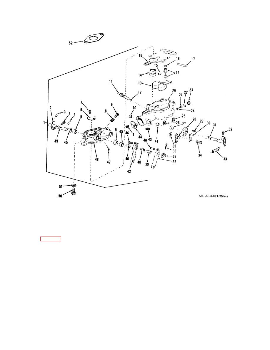
Figure 4-1. Carburetor assembly. Exploded view. |
|
||
| ||||||||||
|
|
 TM 10-3930-621-34
Figure 4-1. Carburetor assembly. Exploded view.
retainer (27) into bores until retainer is flush with
4-5. Assembly and Adjustment
machined surface of fuel bowl.
(3) Insert choke shaft (31) into air intake.
Note. All inspection and checks must be completed
(4) Insert choke plate (6) into air intake making
before assembling carburetor.
certain plate is located in same position in the intake in
regards to the poppet valve as when removed.
a.
Refer to figure 4-1 for all item numbers.
(5) Install throttle stop screws (4) and secure
b.
Install bracket on air intake boss with screw (29).
choke plate (44).
c.
Install clip (30) loosely on bracket.
f. Install shaft return spring (33) to shaft (31) and
d.
Insert plug (10) and drain disk (43) in fuel bowl.
bracket (28).
e.
Install choke assembly as follows:
g. Install the drain plug (26), main discharge jet (11)
(1) Install screw (32) several turns into shaft
and well vent jet (15).
(31).
h. press throttle shaft retainers (45) and seals
(2)
Press
choke
shaft
washer
(41)
and
4-3
|
|
Privacy Statement - Press Release - Copyright Information. - Contact Us |
