 |
|||
|
|
|||
|
|
|||
| ||||||||||
|
|
 protection when using compressed
air.
(1) Clean all parts in approved solvent and dry
using compressed air.
(2) Inspect for worn or damaged springs and
ball seats.
(3) Inspect for damaged threads.
d. Reassembly.
(1) Apply a coat of oil to ball seat. (LO 10-
3930-620-12.)
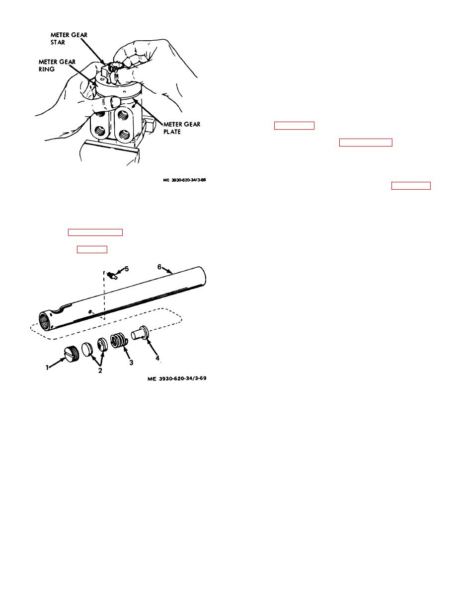
(2) Reassemble drag link internal parts in the
reverse of figure 3-69.
e. Adjustment. The drag link assembly is adjusted,
after installation, according to paragraph 2-20.
3-38. Power Steering Cylinder
a. Removal. Remove the power steering cylinder
(TM 10-3930-620-12).
b. Disassembly.
(1) Remove the lock ring (1, fig. 3-70)
Figure 3-68. Meter gear star being installed.
securing the spacer (2) in position and remove the
spacer.
3-37. Drag Link Assembly
(2) Remove the lock ring (3) securing the
head (4) in the cylinder (15) and remove the head from
a. Removal. Remove the drag link assembly
the cylinder by pulling out the rod and piston assembly.
according to paragraph 2-20.
(3) Carefully slide the head off the rod (14).
b. Disassembly. Remove adjusting plug and
Remove the wiper ring (6), backup ring (7), and packing
internal parts. ( fig. 3-69.)
(8) from the head.
(4) Remove the nut (9) securing the piston
(10) to the rod (14). Slide the piston off the rod.
(5) Remove the backup rings (12) and the
packing (13) from the piston. Remove the rod seal (11)
from the rod.
(6) If the lubrication fitting (17) is damaged,
replace it.
(7) If the bushing (16) requires replacement,
press it out with a suitable tool or arbor press.
c. Cleaning, Inspection and Repair.
(1) Clean the metal parts in a suitable solvent
and dry them with compressed air. Wipe the seals clean,
using hydraulic oil as a solvent.
(2) Inspect the tube bore, rod, head, and
piston for cracks, scratches, scoring or other damage,
and excessive wear. Inspect the seals for damage or
excessive wear.
1 Adjusting plug
(3) Slight imperfections can be cleaned up
2. Ball socket seat (21
with a polishing stone. Replace any damaged or
3. Spring
excessively worn parts.
4. Spring seat
d. Reassembly. Reassemble the cylinder by
5. Lubrication Fitting
reversing the disassembly procedure. Lubricate the
6. Drag link
cylinder parts with a light coating of hydraulic oil. Be
careful not to damage seals against threads or sharp
Figure 3-69. Drag link. exploded view.
edges during reassembly. When installing the head
assembly, compress the lock ring. Keep it compressed
c. Cleaning Inspection.
while sliding the head into the tube until the lock ring can
snap into place.
Warning: Use
an
approved
cleaning solvent. Wear suitable eye
3-79
|
|
Privacy Statement - Press Release - Copyright Information. - Contact Us |