 |
|||
|
|
|||
|
Page Title:
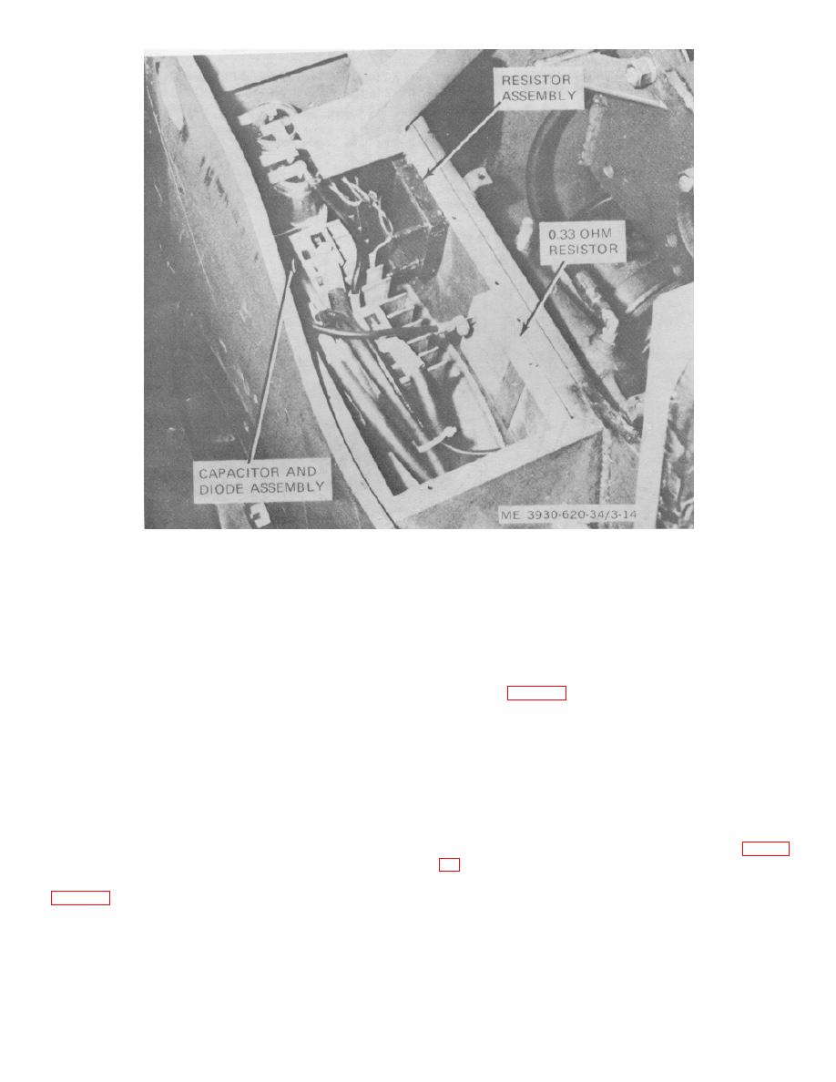
Figure 3-14. Capacitor and diode assembly compartment |
|
||
| ||||||||||
|
|
 Figure 3-14. Capacitor and diode assembly compartment
b. Inspection. Inspect for evidence of damage,
3-9. Power Switch Assembly
overheating, or warping. Inspect around terminals and
a. General.
case for cracks.
(1) Open the power switch cover (TM 10-3930-
c. Resistance Test.
620-12).
(1) Use ohmmeter to measure for zero ohms
(2) Power should be kept off for all of the
between the two terminals numbered 8.
following procedures except for the voltage test of
(2) Measure from one terminal 8 to each other
subparagraph d. Disconnect battery and discharge
terminal, as indicated below. Each resistance value has
capacitors (para 2-5).
a tolerance of 5 %
b. Inspection.
(1) Inspect for dust, dirt, and other foreign
Terminal
Resistance
material in the compartment. Pay particular attention to
2
6 Ohms
the areas between the fins of the heat sinks. Clean
4
55 Ohms
using a vacuum cleaner and brush.
6
25 Ohms
(2) Examine for ant evidence of overheating,
7
33 Ohms
frayed or cracked spires, bulging. or discoloration.
d. Breakdown Test. Using an insulation break-down
c. Resistance Tests. Use an ohmmeter to check
tester, make a high-potential test from case to each
continuity and to measure resistance, as indicated below.
terminal. Test at 1000 volts ac for one minute. There
Reconnect each lead and fuse after checking. (fig. 3-
should be no current leakage.
e. Installation.
Apply silicone grease to the
(1) Remove one end of each accessible wire lead
mounting surface of the resistor assembly and the truck.
and check for continuity (zero ohms resistance ).
nuts and reconnect the leads.
3-25
|
|
Privacy Statement - Press Release - Copyright Information. - Contact Us |