 |
|||
|
|
|||
|
Page Title:
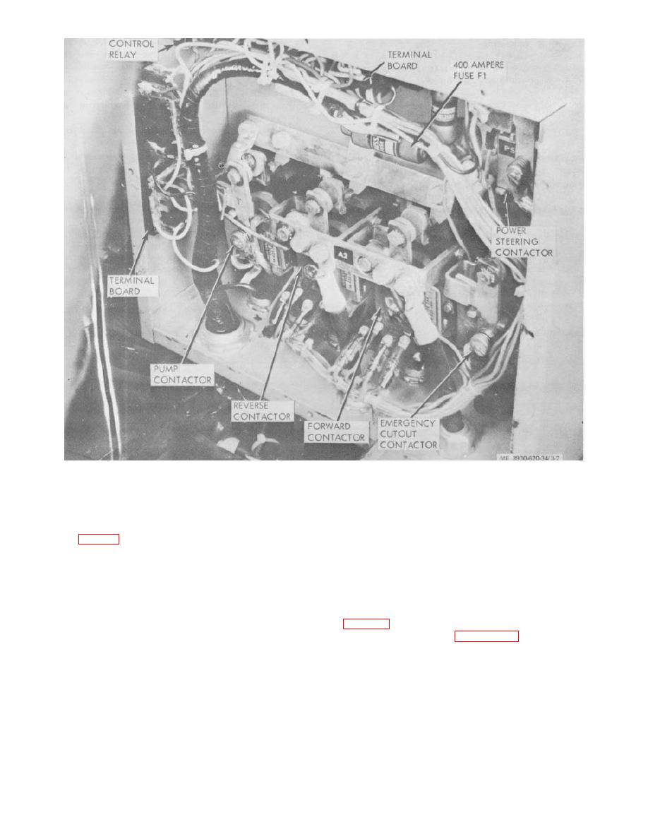
Figure 3-2. Contactor unit, front view |
|
||
| ||||||||||
|
|
 Figure 3-2. Contactor unit, front view
3-5.
Contactor Unit
a. Test.
the accelerator pedal slightly. The reverse contactor (R)
and the control relay must operate.
(1) Use thin cardboard to insulate all four pairs
(5) With the pedal still depressed, more the
of contacts on the forward and reverse contractors (F
directional control switch to the forward (F) position. The
and R). (fig. 3-2.)
reverse contactor and control relay must de-energize.
(2) Turn on the key switch, apply pressure to the
b. Inspection. Visually inspect all components for
seat, and make sure the emergency stop switch is
evidence of wear or damage. Check for cracked or
released. The power steering (PS) and emergency
frayed wires.
cutout (ECI contractors must operate.
c. Disassembly.
(3) Move the directional control switch to the
forward (F) position and depress the accelerator pedal
(1) Disconnect battery and discharge capacitors
slightly. The forward contactor (F) and the control relay
(CR) must operate.
(2) Reference figure 3-3 and disassemble
(4) Release the pedal and move the directional
contactor unit in numerical sequence.
control switch to the reverse (R ) position. Depress unit.
3-4
|
|
Privacy Statement - Press Release - Copyright Information. - Contact Us |