 |
|||
|
|
|||
|
Page Title:
Chapter 3. REPAIR OF POWER PLANT |
|
||
| ||||||||||
|
|
 CHAPTER 3
REPAIR OF POWER PLANT
Section I. REPAIR OF ENGINE ELECTRICAL SYSTEM
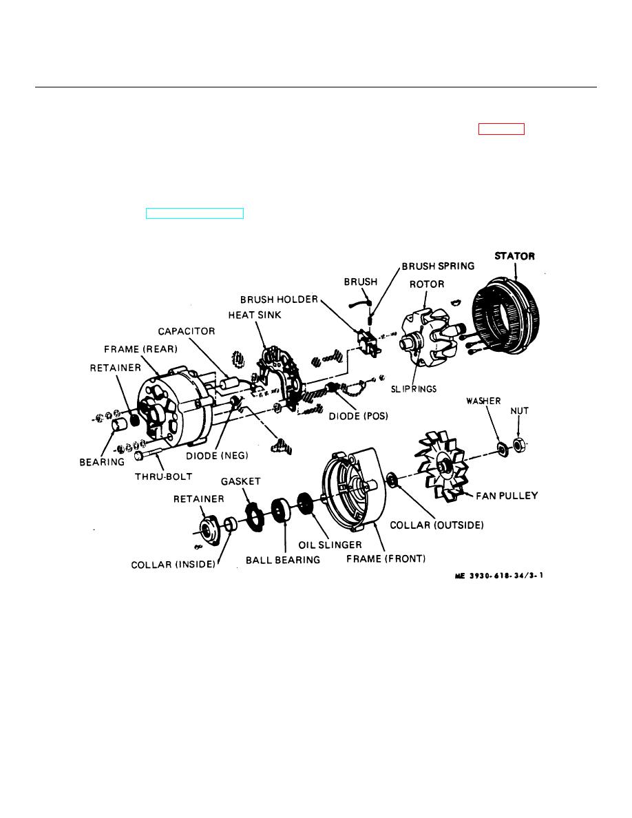
b. Disassembly. Refer to figure 3-1.
3-1. General
(1) Remove the four thru-bolts from the
This section contains information useful to direct
and
alternator assembly
general support maintenance personnel in their
NOTE
performance of maintenance of the engine electrical
system.
Place a scribe mark on the stator and
3-2. Alternator
end frames to aid in locating the
a. Removal and Installation. Remove or install the
parts in the same position during
alternator as directed in TM 10-3930-618-20.
reassembly.
Figure 3-1. Alternator, exploded view.
(2) Separate the front end frame and the rotor
(4) Separate the rotor from the front end
assembly from the stator assembly. Pry them apart at
frame, removing key.
the stator slot with a screw driver.
(5) Remove retainer, collar, gasket and
(3) Place the rotor in a vise and tighten just
bearing from end frame.
enough to permit removal of the shaft nut. Remove the
(6) Remove stator from rear end frame.
shaft nut, washer, pulley, fan and collar.
(7) Remove rear end frame bearing and
3-1
|
|
Privacy Statement - Press Release - Copyright Information. - Contact Us |