 |
|||
|
|
|||
|
|
|||
| ||||||||||
|
|
 UPRIGHTS
the upper crossmember and one is on the front.
The hoist cylinder is supported by the lower
crossmember.
Attached to the crossmember and
The front latch and the right rear latch are splined and
positioned in back of the cylinder are two shim-adjusted
pads on which the inner and intermediate uprights rest.
pinned to a common shaft. Also on the front of the
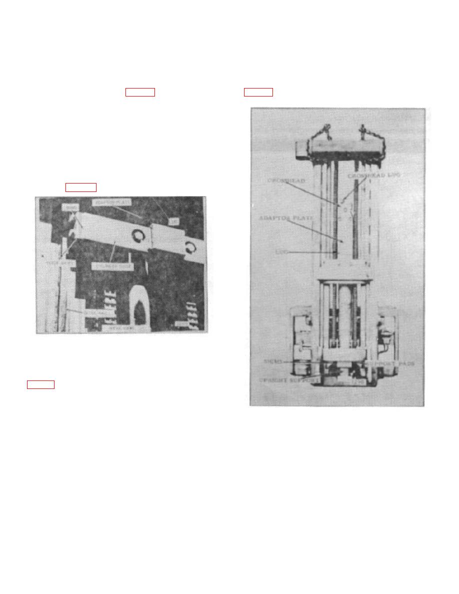
same crossmember is a lug. (Fig. 20)
Situated on the inside front face at the top of each rear
channel flange is a shim-adjusted strip bearing. In front
of these bearings are two load rollers. Two more rollers
are located at the bottom, one on the outer side of each
channel.
Welded to the back of each channel is a cylinder guide
rail. Sliding on the rails is a cylinder guide. The guide is
shim-adjusted to the rails to slide freely with minimum
looseness. (Fig. 22)
Figure 22.
Outer Upright: A shim-adjusted strip bearing is located
on the front face at the top of each rear channel flange.
roller. In the same vicinity and attached to the back is a
stop plate. This plate is in line with the stop block on the
intermediate upright.
Figure 23.
Located on the front of the upper crossmember is a lug,
In the lowered position: The carriage is free to travel up;
which works in conjunction with the latching mechanism.
the inner upright is latched to the intermediate; the
intermediate upright is latched to the outer. The left
latch engages the intermediate upright and a right latch
engages the outer upright. Each latch is locked in
position by the adjacent latch.
At the beginning of the first stage of operation, the
B-182
|
|
Privacy Statement - Press Release - Copyright Information. - Contact Us |