 |
|||
|
|
|||
|
|
|||
| ||||||||||
|
|
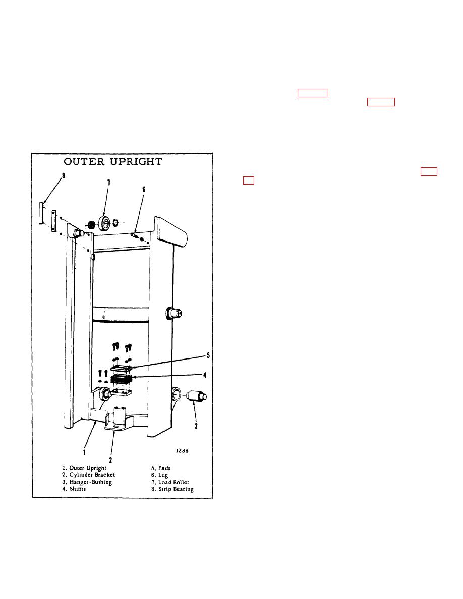
 UPRIGHTS
Basically this assembly is made of three uprights: outer,
front of the upper crossmembers of the intermediate
inner and intermediate.
and outer uprights. These, when engaged by latches,
secure the three uprights together. The remainder of
A latching mechanism is utilized to keep the uprights in
the lugs, one on the back of the crosshead, one on the
the proper operating sequence.
There are seven
adapter plate (Fig. 21) and one on the back of the
latches, all of which are located on the upper members
upper crossmember of the carriage (Fig. 18) trigger the
of the inner and intermediate uprights.
latching mechanism at the proper time to release one
upright from the other. A sixth lug, located on the back
Working in conjunction with the latches are five lugs
of the left vertical member of the carriage, is a safety
(socket head capscrews). Two of these are located in
lug and does not function with the latch mechanism.
Inner Upright: Besides the latches, the inner upright has
two load rollers, four chain sheaves and a box. The box
is welded to the front of the upper crossmember. (Fig.
upright, one on each outer side. Located on each side
of the box is a chain sheave. The other two sheaves
are located on the lower crossmember. The brackets to
which these sheaves are attached have guards that
prevent the load chains from jumping off the sheaves
under certain operating conditions.
Of the four latches on the inner upright, two are located
in back of the upper crossmember, one Is in the box,
and the other is in front of the box.
Looking from the driver's seat, the two right latches
(front and rear) are splined and pinned to a common
shaft. The same is true for the left latches. The latch in
the box is in line with a lug on the crosshead. The latch
on the front of the box is in line with a lug on the
carriage.
Welded on the front of the box is a block. This block is
a stop, which when contacted by a block on the carriage,
prevents further raising of the carriage.
Intermediate: Of the three latches on the intermediate
upright, two are on the back of
Figure 21.
B-181
|
|
Privacy Statement - Press Release - Copyright Information. - Contact Us |