 |
|||
|
|
|||
|
|
|||
| ||||||||||
|
|
 UPRIGHTS
NOTE:
THREE-STAGE UPRIGHT ASSEMBLY
A length of wood 2 x 2 maybe inserted into
the top of the primary rod to aid in guiding
A. GENERAL
the rod out of the shell.
Besides a three-stage hoist cylinder, a crosshead and
5. Support the primary rod at both ends in a
guide assembly and a carriage, the three-stage upright
horizontal position. Remove the spiral lock from above
is made up of three upright assemblies: (1) Inner
the bushing at the bottom of the primary rod. Push the
Upright(2)Intermediate Upright (3) Outer Upright. The
bushing toward the top of the rod and remove the ring
crosshead and guide assembly includes a crosshead,
from the rod. Slide the bushing off.
adapter plate, and a cylinder guide.
D. CLEANING AND INSPECTION
CARRIAGE
1. Clean all parts in solvent. Stand the secondary
A. GENERAL
rod on end to allow oil and solvent to drain from above
the packing.
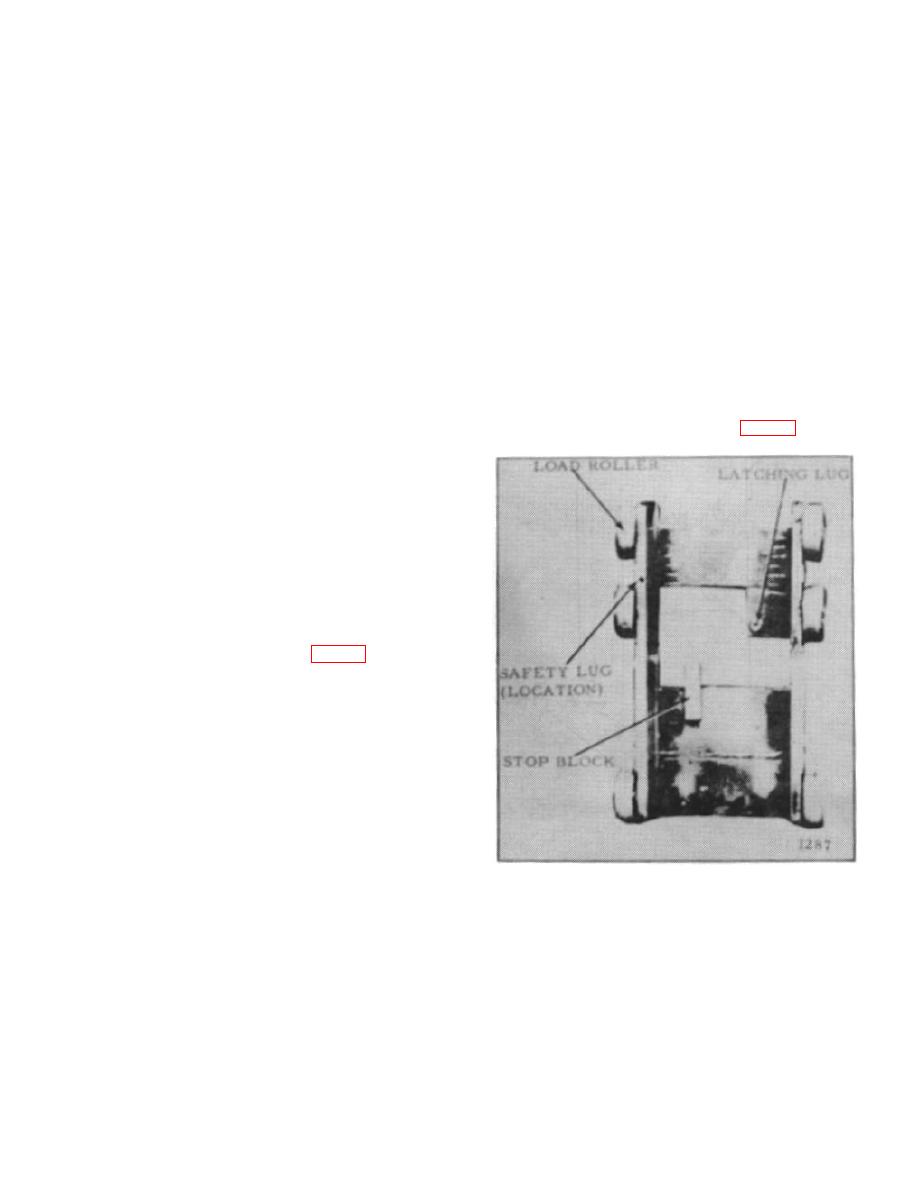
This is a hook-type assembly equipped with shim-
adjusted canted load rollers. It is also equipped with a
2. Check packing for rounded, worn, scratched or
lug and lifting block that works in conjunction with the
torn lips.
When installed in the primary bushing
latching mechanism on the uprights. (Fig. 18)
retainer, the packing should extend beyond the retainer.
The secondary packing should extend beyond the
piston. Replace packing if deteriorated, mutilated or if it
does not extend beyond its respective retainer or piston.
3. Check the rods for nicks, burrs, scratches and
rust.
Slight defects may be removed with fine
sandpaper. However, do not sand chrome plating off
the outside of either rod. Chrome plating on the rods
can be checked by applying copper sulfate to the rod.
The rod will discolor where the chrome is gone and
should be replated or replaced.
E. ASSEMBLY AND INSTALLATION (Fig. 17)
1. Assembly of the cylinder is in reverse of order in
which it was disassembled. Lubricate all parts during
assembly.
2. Install the base in its original position, being
careful not to damage the O-ring and back-up ring.
3. Pour two pints of hydraulic oil with rust inhibitor
additive into the cavity between the primary and
secondary rods, before screwing the bushing into the top
of the primary rod.
Figure 18.
4. After the cylinder is installed, adjust the load
chains.
B-179
|
|
Privacy Statement - Press Release - Copyright Information. - Contact Us |