 |
|||
|
|
|||
|
|
|||
| ||||||||||
|
|
 UPRIGHTS
A. GENERAL
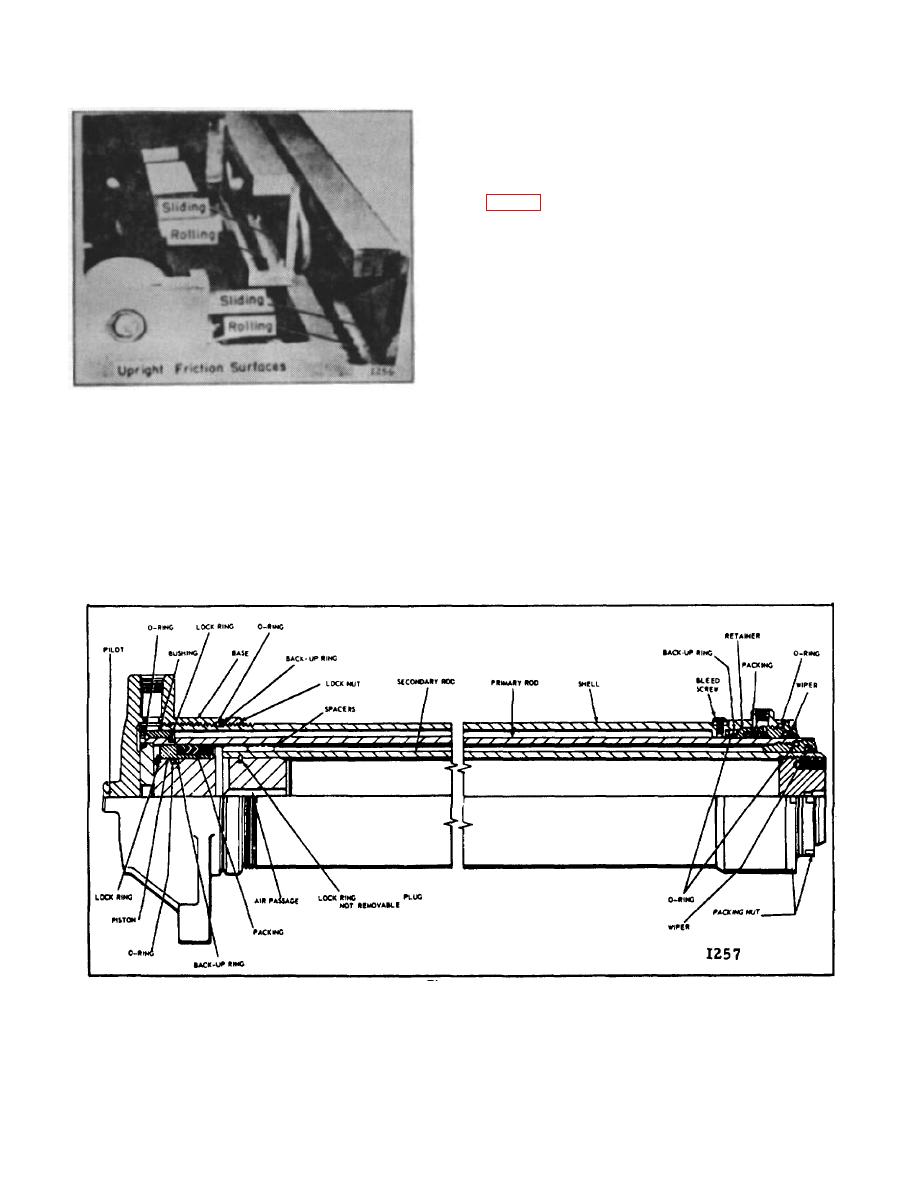
The three-stage hoist cylinder used on the free lift and
three-stage uprights is made up of four components: (1)
Shell, (2) Primary Rod, (3) Secondary Rod, (4) Base.
The shell is threaded at both ends. A packing nut is
screwed into the internal threads at the top and the base
is screwed onto the external threads at the bottom.
Relationship between base and shell is secured by a
lock nut. Located near the top of the shell is a bleed
screw and a leak-off fitting.
A bushing secured to the bottom of the primary rod and
a packing nut at the top centers the rod in the shell.
Self-adjusting packing at the top of the cylinder provides
Figure 16.
the necessary high pressure seal between the primary
rod and outer shell.
of the uprights.
Also, higher than normal hydraulic
pressure will be needed to lift a given load.
The secondary rod is centered in the primary rod by a
self-adjusting packing assembly secured to the bottom
F. INSTALLATION
of the secondary rod and a bushing and seal assembly
screwed into the top of the primary rod.
Reverse removal procedure.
The outside diameters of both rods are chrome plated to
HOIST CYLINDER
retard oxidizing when exposed to the atmosphere.
Figure 17.
B-177
|
|
Privacy Statement - Press Release - Copyright Information. - Contact Us |