 |
|||
|
|
|||
|
|
|||
| ||||||||||
|
|
 TRANSMISSION
7.
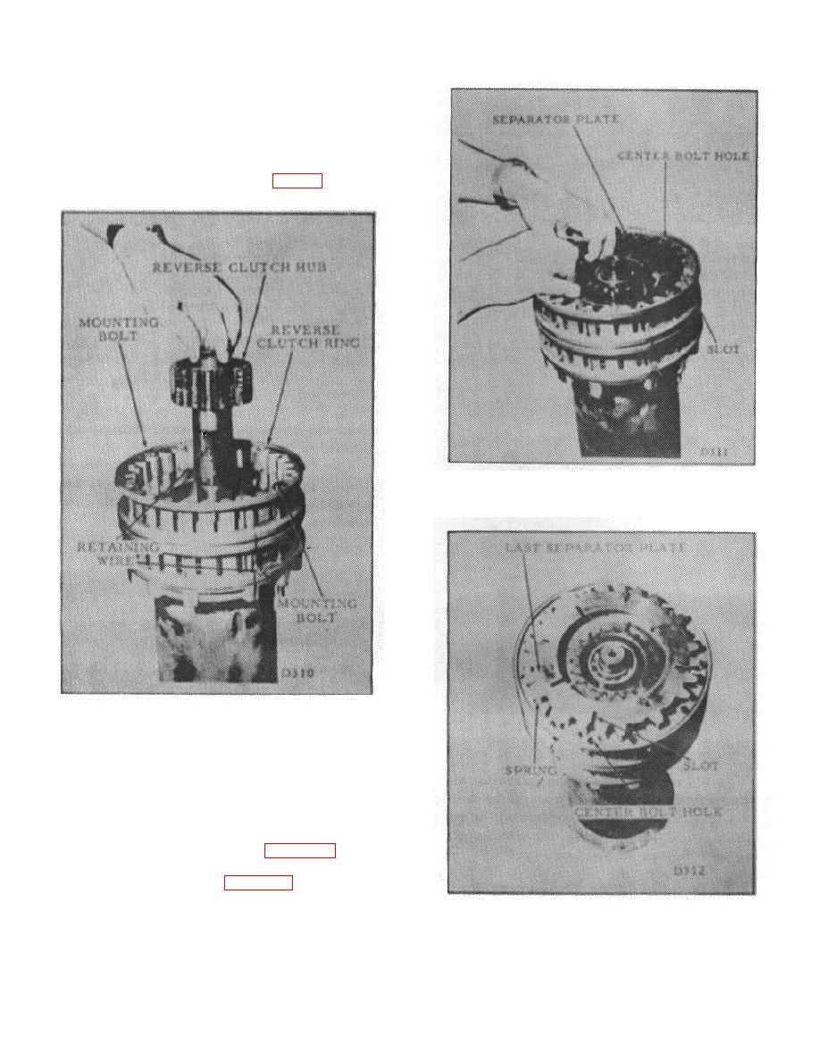
Position the reverse clutch ring on top of the
pressure plate. Align the bolt holes and hold them in
alignment with two mounting bolts. Compress the
forward clutch pack together by applying pressure to the
reverse clutch ring; retain the pack in this position with
two wires placed 1800 apart. Lower the reverse clutch
hub into the center of the assembly. (Fig. 28)
Figure 29.
Figure 28.
8.
Beginning with a friction disc alternately
install all the remaining friction discs and all the
separator plates, except for the last one. Make sure the
plates all dish in the same direction.
NOTE: All but the last separator plate
are installed as shown in Figure 29.
Place the last plate on top of the
springs as shown in Figure 30.
Figure 30.
B-104
|
|
Privacy Statement - Press Release - Copyright Information. - Contact Us |