 |
|||
|
|
|||
|
|
|||
| ||||||||||
|
|
 ENGINE
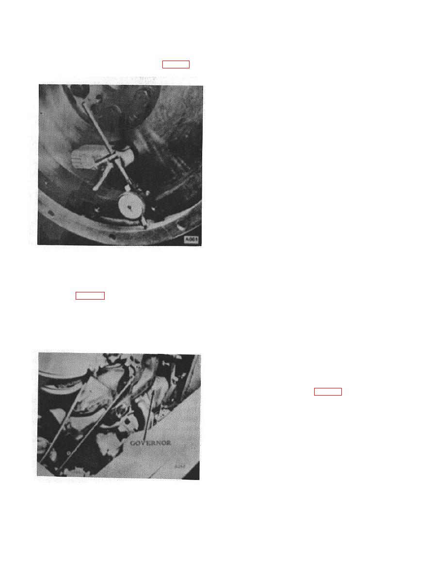
cator to contact the housing bore and check in the same
manner. The same runout limit prevails. (Fig. 60)
ernor shaft on two hardened steel races. One race is a
flat surface, the other conical in shape. As the balls
move in and out they tend to raise or lower the conical
shaped race, the motion of which is transferred through
a fork or finger to the governing lever on the outside of
the governor housing. The force created by the balls in
their centrifugal movement is opposed by a spring on
the governing lever, the other end of which is hooked to
the speed adjusting screw lever, The balls move in a
slotted driver which is pinned to the governor shaft; the
two races are free floating on the shaft. When the
engine is running at a fixed speed, all parts go around
with the governor shaft and the thrust is taken on the
thrust bearing between conical shaped race and fork
base. When a change in speed due to change in load
takes place, the relative speed between the balls and
races is changed. Consequently, wear is distributed
over the entire operating surface of the races and balls.
Since the surfaces are hardened, little or no wear other
than a polish should ever take place on the parts.
B. ADJUSTMENT
\
Figure 60.
The hook-up of governor lever to carburetor lever
should be done in the following manner:
GOVERNOR
1. Make sure carburetor shaft does not stick nor
A. GENERAL (Fig. 61)
bind.
This governor differs from conventional centrifugal
2. With governor lever in its normal position under
governors principally in that round steel balls are used
spring tension, with engine shut-off, with carburetor
as the motivating force producer instead of masses of
lever in wide open throttle position, a rod of exact length
weight. The balls move out and in radially from the gov
to connect the two levers is inserted.
3. Make sure there is no bind nor sticking in the
assembly of rods and levers. This is very important
4. The spring tension is adjusted by repositioning
the spring anchor nuts. (Fig. 62)
Figure 61.
B-21
|
|
Privacy Statement - Press Release - Copyright Information. - Contact Us |