 |
|||
|
|
|||
|
|
|||
| ||||||||||
|
|
 OPERATING INSTRUCTIONS
2. Upright Control Lever.
The hoist and tilt
checked by an Ammeter gauge. The Ammeter may
functions of the upright are controlled by one lever. The
show a slight discharge at engine idle, but should
shift pattern for this lever is shown on the lever knob.
indicate charging when the engine speed is increased.
3. Parking Brake Lever. All trucks are equipped
2. Engine oil pressure is indicated by a pressure
with a parking brake handle to the right of the steering
gauge. The gauge may register high pressure when the
column. Pulling up on the lever sets the brake.
engine is first started in cold weather, but the pressure
should drop to its normal level as the engine warms up.
Always stop the engine immediately if the gauge
C.
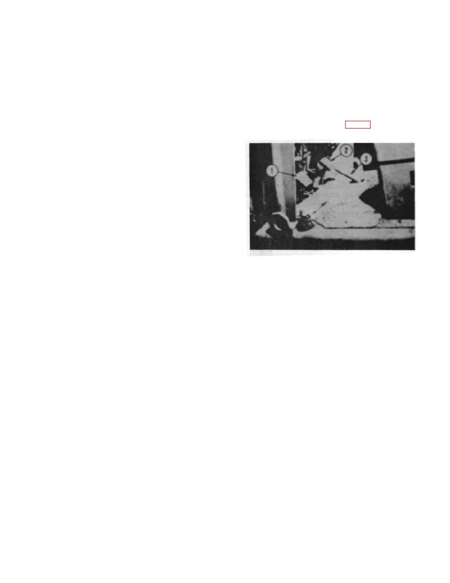
FOOT PEDAL LOCATION (Fig. 2)
indicates no pressure when the engine is running.
3. The hour meter, designated ENGINE HOURS,
registers the accumulated operating hours of the engine.
Periodic maintenance recommendations are based on
these engine hours.
4. The TEMP gauge indicates the engine coolant
temperature.
5. The transmission oil temperature is indicated by
a TRANS TEMP warning light. When the transmission
oil temperature is too high for safe operation the light
will come on.
6. The fuel gauge indicates the level of fuel in the
tank.
Figure 2.
7. Pulling the CHOKE knob facilitates starting the
1. The Inching pedal, sometimes referred to as left
engine on gasoline powered trucks.
brake pedal, is located to the left of the steering column.
By adjusting the pedal position with the left foot the
8. The Ignition Switch is a two position, ON-OFF,
operator can control the truck movement in small
unit.
increments (inching) at high engine speed. Complete
application of the pedal places the transmission in
9. The Starter control is a push-button.
neutral and sets the service brakes,
10. The Light Switch is a pull-on type.
2. Brake pedal. This pedal is located to the right of
the steering column and is operated by the right foot.
B.
CONTROL LEVERS
The brake pedal is independent of the inching pedal and
has no connection with the transmission. The brake
1. Shifting Levers
pedal should be used for braking only and not for
inching.
a. The single-speed power shift transmission
has one lever mounted on the right side of the steering
3. The Accelerator pedal is located to the right of
column for Forward - Neutral - Reverse selection.
the brake pedal. Truck speed is controlled with the right
foot.
CAUTION: Do not operate a powershift
A-6
|
|
Privacy Statement - Press Release - Copyright Information. - Contact Us |