 |
|||
|
|
|||
|
Page Title:
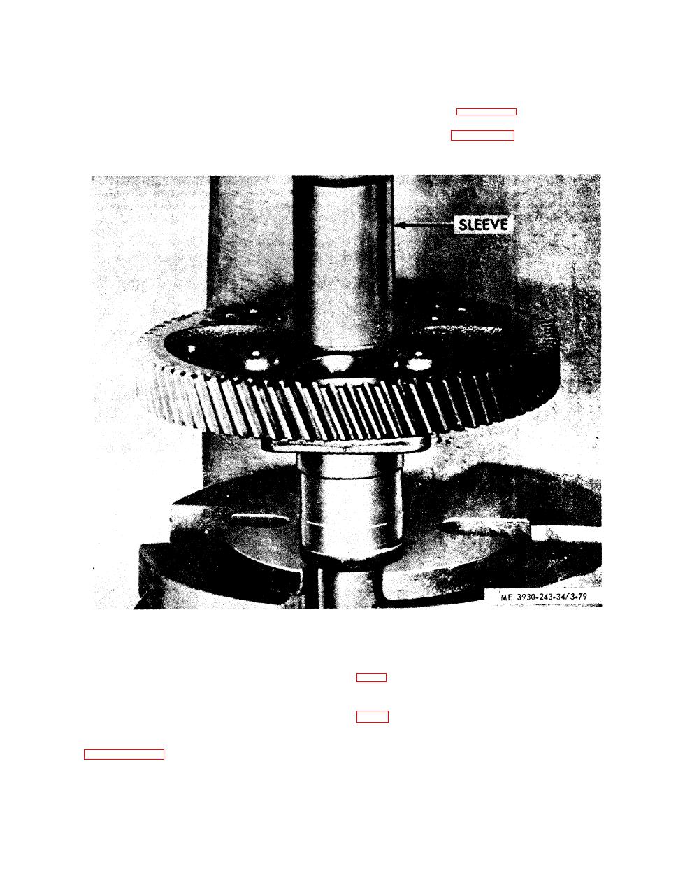
Figure 3-79. Camshaft gear installation |
|
||
| ||||||||||
|
|
 b e a r i n g s from the front to the rear of
f. Sequence for Installing Bearings.
the block.
CAUTION
g. Reassembly.
All replacement bearings must be in-
(1) Refer to figure 3 - 7 9 a n d i n s t a l l t h e
stalled with the notch located at the
camshaft gear onto the camshaft.
s a m e position in the original bearings.
(2) Refer to figure 3 - 7 8 a n d r e a s s e m b l e
and front
T h e f r o n t intermediate
camshaft. Reassembly is the reverse order of
b e a r i n g s are installed by pressing the
disassembly.
(3) Install the upper engine front cover (para
h.
Installation.
(1) Lubricate bearings and shafts with engine
( 4 ) Secure the thrust washers in place and
oil and slide the shaft assemblies into the cylinder
tighten the bolts to 30-35 foot-pounds torque (fig.
block being careful not to damage the bearings or
t h e cams and journals. Make sure that the ap-
(5) Install the front balance weights.
propriate timing marks on the gears are aligned.
" G e a r Train and Engine Timing" is covered in
(6) Attach the gear nut retainer plates to the
gears with bolts and lockwashers and tighten the
bolts to 35-39 foot-pounds torque.
(2) Slide an oil slinger on the front end of both
shafts.
( 7 ) Check the clearance between the thrust
|
|
Privacy Statement - Press Release - Copyright Information. - Contact Us |