 |
|||
|
|
|||
|
|
|||
| ||||||||||
|
|
 (7) Install various parts and assemblies
(4)
Install a woodruff key in each shaft.
previously removed as outlined in their respective
(5)
Install pulleys on the shaft.
paragraphs of the manual.
(6)
Install and tighten pulley retaining nuts to
300-325
foot pounds torque.
(6) Remove the bolts which secure the gear nut
retainer plates (fig. 3-72) to the gears; then remove
a. General. T h e c a m s h a f t a n d b e a r i n g s a r e
the retainer plates.
located just below the top of the cylinder block. The
(7) Wedge a clean rag between the gears as
camshaft is described in paragraph 3-28.
shown in figure 3-73; then, remove the nuts from
b. Removal of Camshaft.
each end of both shafts with a socket wrench.
NOTE
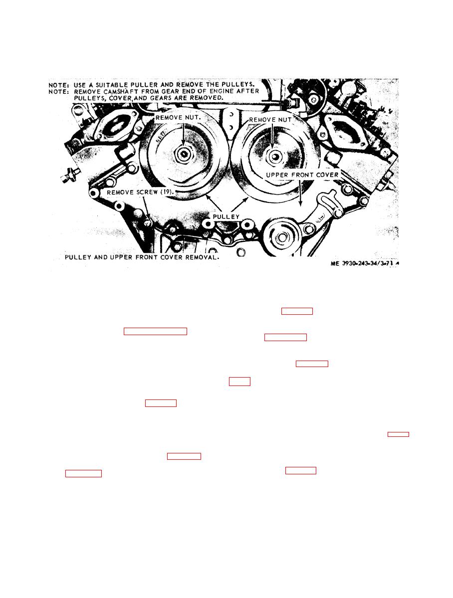
( 8 ) Remove camshaft pulley from the front
Whenever an engine is being completely recon-
end of the shafts (fig. 3-74).
(9) Remove the upper engine front cover (para
on the shafts need replacing, the shafts should be
removed from the engine in the following manner:
(10) Remove the oil slinger from the front end
(1) Drain the engine cooling system.
of both shafts.
( 2 ) Remove the engine (para 2-9), and at-
(11) Remove the two thrust washer retaining
t a c h i n g p a r t s n e c e s s a r y t o m o u n t e n g i n e on
bolts securing the camshaft or balance shaft thrust
overhaul stand.
washer to the cylinder block, by inserting a socket
(3) Mount the engine on an overhaul stand. B e
wrench through a hole in the web of the gear (fig. 3-
sure the engine is securely mounted on the stand
75).
before releasing the lifting sling.
(12) Withdraw the shaft, thrust washer, and
( 4 ) Remove the cylinder head (para 3-19).
g e a r , as an assembly, from the rear end of the
( 5 ) Remove the flywheel and the flywheel
c y l i n d e r block (fig. 3-76).
h o u s i n g (para 3-21 and 3-22).
|
|
Privacy Statement - Press Release - Copyright Information. - Contact Us |