 |
|||
|
|
|||
|
Page Title:
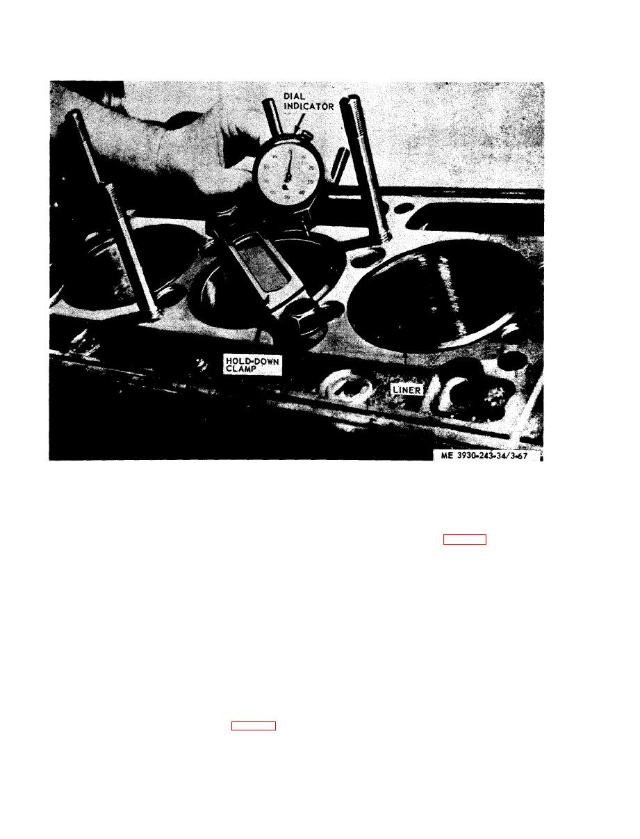
Figure 3-67. Checking distance of line flange below top face of cylinder block. |
|
||
| ||||||||||
|
|
 and rod assembly on the liner, so that the numbers
4. Match mark the liner and block with
on the rod and cap are aligned with the match mark
chalk or paint the serial number side of engine to
on the liner (operation 2, fig. 3-68).
insure the liner is reinstalled in same position in the
same bore.
NOTE
5. Remove holddown clamp and litter.
The numbers, or number and letter on the side of the
rod and cap identify the rod with the cap and indicate
e. Reassembly.
the cylinder in which they are to be used. If new rods
( 1 ) With the piston assembled to the con-
are used, etch or stamp the same identification, in the
necting rod and the piston rings in place, apply
same location as on the connecting rod replaced.
clean engine oil to the piston, rings, and the inside
(7) Push the piston and rod assembly down
of the piston ring compressor.
into the liner until the piston is out of the com-
(2) Place ring compressor on a woodblock with
pressor.
taper end up.
CAUTION
(3) Stagger the piston ring gaps properly on
D o not force the piston into the liner.
the piston. Insure that oil control ring expanders
The expanders apply considerable
are not overlapped.
force on the oil ring; therefore, extra
(4) Start the piston straight into the ring
care
must be taken
during the
c o m p r e s s o r and push the piston down until it
"loading" operation to prevent ring
contacts the wood block (operation 1, fig. 3-68).
breakage.
(5) Note position of the matched mark on the
(8) Remove the connecting rod cap and the
liner and place the liner on a block of wood.
ring compressor.
(6) Place the ring compressor and the piston
|
|
Privacy Statement - Press Release - Copyright Information. - Contact Us |