 |
|||
|
|
|||
|
Page Title:
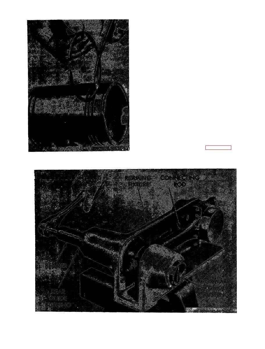
Figure 3-61. Measuring piston ring side clearance. |
|
||
| ||||||||||
|
|
 lock caused by fuel or water leakage to the piston
crown may result in a bent and possible broken
connecting rod.
(b) Check the connecting rods for cracks.
(c) Inspect and open holes in spray nozzle at
upper end of connecting rod, if necessary. Blow dry,
compressed air through drilled oil passage in rod
nozzle to be sure all passages are open.
(d) Check rod bushings for signs of scoring
or other damage.
(e) Measure the outside diameter of piston
pin to determine wear. The standard diameter of
new piston pins is 1.3746 to 1.3750 inches.
(f) The standard inside diameter of a new
bushing in a connecting rod is 1.3760 to 1.3765
inches. The specified clearance between the piston
pin and bushing in upper end of connecting rod is
0 . 0 0 1 0 to 0.0019 inch with new parts, and the
allowable wear limit 0.010 inch. The piston pin
and/or rod bushings must be replaced if the above
limits are not obtained.
(g) Visual inspection, as well as the
dimensional measurements will be made to
determine whether used bearings are satisfactory
for further service or must be replaced. Ream new
piston bushings as illustrated in figure 3-62.
|
|
Privacy Statement - Press Release - Copyright Information. - Contact Us |