 |
|||
|
|
|||
|
Page Title:
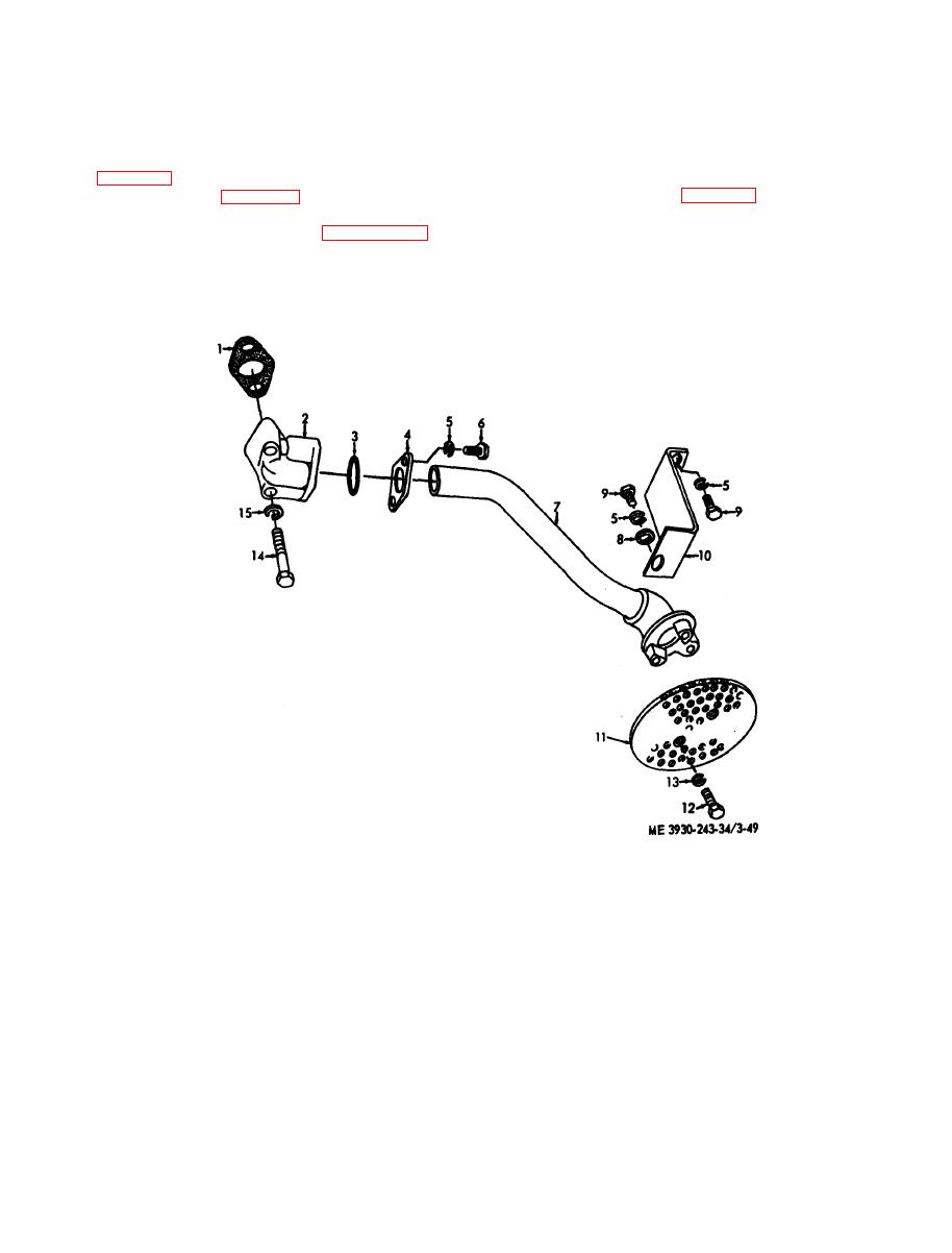
Figure 3-49. Oil pump screen and inlet pipe, disassembly and reassembly. |
|
||
| ||||||||||
|
|
 ( 2 ) Inspect inlet pipe for deep dents and
formed on the inlet side of the pump and oil is
cracks.
drawn from the crankcase through the oil pump
( 3 ) Inspect mounting hardware and screen
screen and inlet pipe into the rotor compartment of
assembly for damage.
the oil pump.
e. Installation.
b. Removal.
(1) Install inlet pipe and oil pump screen (fig.
(1) Drain the engine oil and remove the oil pan
3-2 B).
(2) Install oil pan (para 3-24).
(2) Refer to figure 3-2B and remove the inlet
( 3 ) Refer to current lubrication o r d e r a n d
pipe and oil pump screen.
service the engine lubrication system.
disassemble the oil pump screen and inlet pipe.
d. Inspection.
(1) Inspect the inlet pipe and screen for
evidence of clogging.
1 Gasket
9 Bolt
10 Support
2 Elbow
11 Screen
3 Ring
12 Screw
4 Flange
13 Washer
5 Washer
14 Bolt
6 Bolt
7 Tube assembly
15 Washer
8 Washer
spray. Each piston is fitted with six piston rings.
Cylinder Liner
Four compression rings are placed above the piston
pin and two, three piece oil-control rings are placed
a. General. The top of the piston forms the
below the pin to scrape off excess oil thrown onto
c o m b u s t i o n chamber bowl and is designed to
the cylinder liner. The connecting rod connects the
compress the air into close proximity to the fuel
|
|
Privacy Statement - Press Release - Copyright Information. - Contact Us |