 |
|||
|
|
|||
|
Page Title:
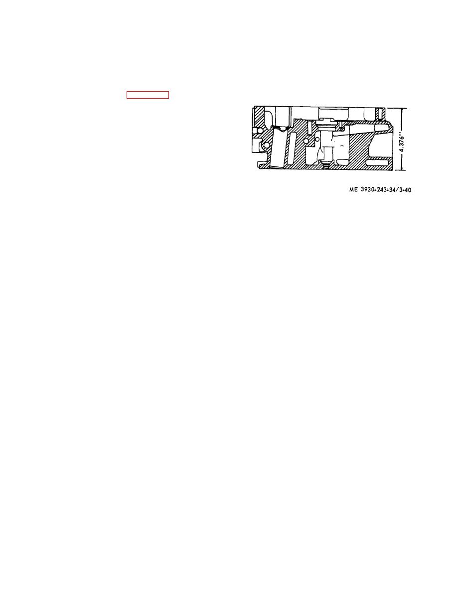
Figure 3-40. Minimum distance between top and bottom faces of cylinder head. |
|
||
| ||||||||||
|
|
 head, the amount of stocked removed should be
(c) Press nozzles into place with outlet holes
stamped on the face of the fire deck near the outer
positioned t o w a r d l o n g i t u d i n a l c e n t e r l i n e o f
edge of the head, in an area not used as a sealing
cylinder head. The angle between outlet holes in the
n o z z l e is 90. Nozzles should be from flush to
surface. Not over 0.002 inch of metal should be
1/32 inch below bottom surface of cylinder head,
removed from the fire deck of any cylinder head.
otherwise interference with proper seating of the
The distance from the top deck to the bottom (fire
head on the cylinder may be encountered.
deck) of the cylinder head must not be less than
4.376 inch as shown in figure 3-40. After a cylinder
head has been refaced, and new injector tubes have
been installed, the cylinder head should be
pressured checked. The top surface of the cylinder
block will not warp to the extent that machining
will become necessary, therefore, no warpage limits
or machining limits are required.
(3) Inspect cylinder head for leaks using the
following procedure:
(a) Seal off the waterholes in the head, using
s t e e l plates and suitable rubber gaskets held in
place by bolts.
(b) Install dummy or scrap injectors to
i n s u r e seating of the injector hole tubes. The
dummy injectors may be made up with old injector
of cylinder head.
n u t s and bodies, the injector spray tip is not
e. Assemble Cylinder Head. New service cylinder
necessary. Tighten the injector clamp bolt to 25-30
heads, for replacement purposes, are equipped with
foot-pounds torque.
valve guides, valve seat inserts, exhaust manifold
(c) Apply 80-100 psi air pressure to water
s t u d s , water nozzles, injector hole tubes and
j a c k e t by drilling and tapping into one of the
waterhole cover plates for an air hose connection.
necessary plugs.
Immerse the head in a tank of water previously
CAUTION
heated
to
180-200F.
for
20
minutes
to
When installing the plugs in the fuel
thoroughly heat the cylinder head.
manifolds apply a small amount o f
(d) Observe the water in the tank for bub-
s e a l a n t to thread of plugs only. Work
bles indicating cracks or leaks.
sealant into threads and wipe off excess
w i t h a clean, lint-free cloth so that
(e) Replace any leaking injector hole tubes.
If inspection reveals cracks in the cylinder head, it
sealant will not be washed into the fuel
should be replaced.
system and result in serious damage to
( 4 ) Inspect cam follower bores in cylinder
the injectors. If the old cylinder head is
head for scoring or wear. Light score marks may be
t o be reused, the parts listed below
cleaned up with crocus cloth wet with fuel oil. If
should be installed in the old head prior
bores are excessively scored or worn so that cam
to assembling the head on the cylinder
f o l l o w e r - t o - h e a d clearance exceeds 0.006 inch,
block.
replace the cylinder head.
(1) Install exhaust valves and springs.
(2) Install push rod assemblies, cam followers,
(5) Inspect the valve seat inserts for cracks or
cam follower guides, rocker arm shaft and rocker
burning. Also, check the valve guides for scoring,
arms.
(6) Inspect water nozzles for tightness. Water
n o z z l e s are used only in the passages between
( 3 ) Place new washers on fuel connectors;
then install fuel connectors and tighten to 20-28
cylinders. To install or replace cylinder head water
foot-pounds torque.
nozzles:
(4) Install fuel injectors at this time or after
(a) Be sure water inlet ports in bottom of
installing cylinder head.
head are clean and free of scale. Water holes may
f. Preinstallation I n s p e c t i o n . The following
be cleaned up with a 5/8 inch diameter drill. Break
inspections should be made just prior to installing
the edges of the holes slightly.
the cylinder head on the engine. These inspections
(b) Check for press fit of nozzles in cylinder
s h o u l d be made whether the head was removed
head. If water holes in head have been enlarged by
f r o m the engine for servicing only the head
corrosion, use wooden plug or other suitable tool to
assembly, or to facilitate other repairs to the engine.
expand nozzle, so that they will remain tight after
installation.
|
|
Privacy Statement - Press Release - Copyright Information. - Contact Us |