 |
|||
|
|
|||
|
Page Title:
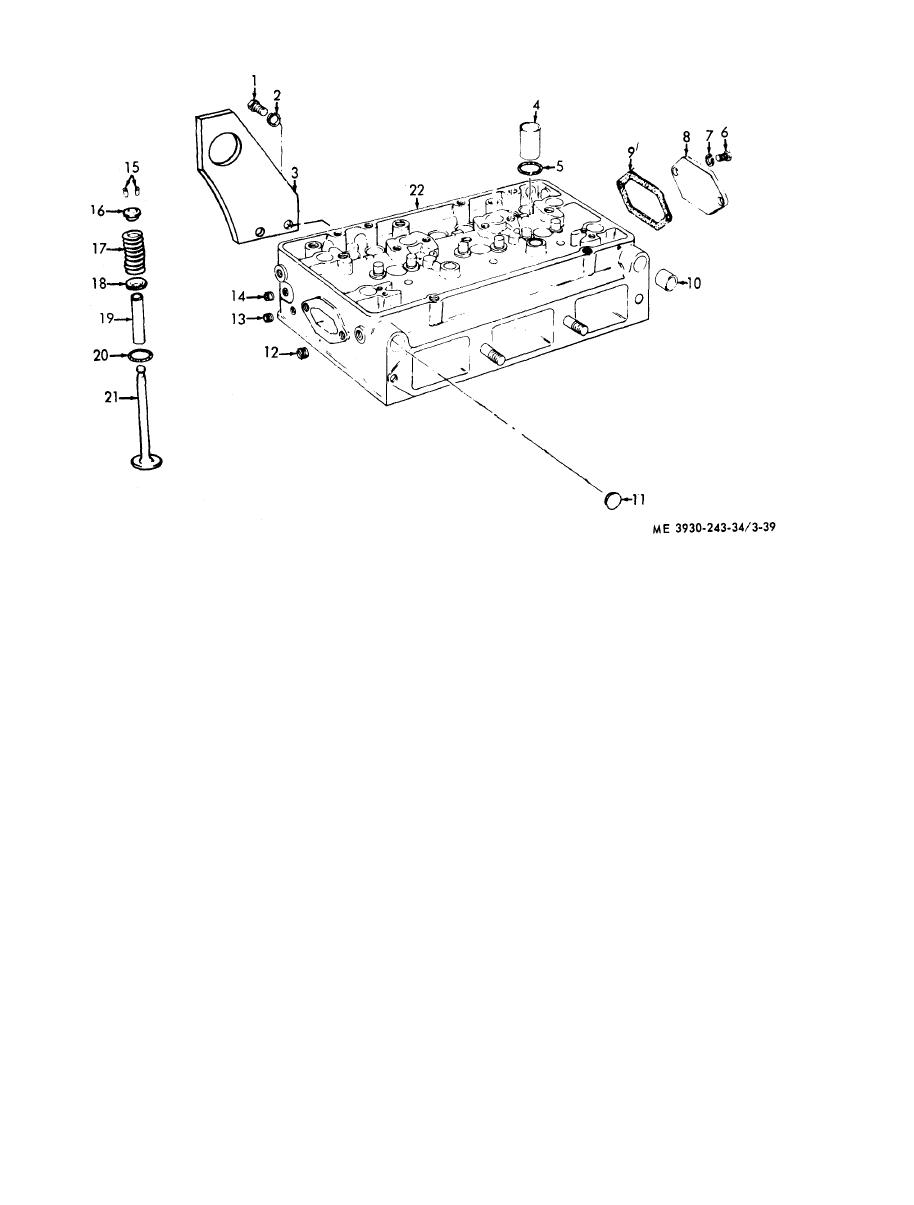
Figure 3-39. Cylinder head and valve assembly, disassembly and reassembly. |
|
||
| ||||||||||
|
|
 1
Bolt
12
Plug
2
Lockwasher
13
Plug
3
Bracket
14
Plug
4
Tube
15
Lock
5
Seal
16
Seat
6
Screw
17
Spring
7
Washer
18
Seat
8
Cover
19
Guide
9
Gasket
20
Seat
10
Plug
21
Valve
11
Plug
22
Cylinder head
d. Inspection.
(a) Using an accurate straightedge and
( 1 ) After the cylinder head has been stripped
feeler gage, check for transverse warpage at each
of all component parts it should be thoroughly
end and between all cylinders.
s t r a i n e d clean. Remove all rust proofing compound
(b) Check longitudinal warpage in six
f r o m a service cylinder head. A simple method of
places. Maximum allowable warpage is given
removing the rust proofing compound is to immerse
below.
the head in P-D-680 solvent, oleum, or fuel oil and
M a x i m u m Longitudinal
M a x i m u m Transverse
clean with a soft bristle brush.
Warpage
Warpage
( 2 ) Over a prolonged period of operation, the
0.005 inch
0 . 0 0 4 inch
c y l i n d e r head may assume a contour to match that
of the cylinder block, which is normal. However, if
The maximum allowable warpage limits should be
t h e cylinder head is allowed to become overheated
u s e d as a guide in determining the advisability of
because of coolant loss, the resultant high tem-
r e i n s t a l l i n g the head on the engine or refacing it,
perature cause stresses to occur in the casting which
The number of times a cylinder head may be
w i l l affect the flatness of the head. Therefore, the
r e f a c e d will, of course, depend upon the amount of
b o t t o m (fire deck) of the cylinder head should be
stock removed from the head during previous
checked for flatness as follows:
reworking operations. When refacing a cylinder
|
|
Privacy Statement - Press Release - Copyright Information. - Contact Us |