 |
|||
|
|
|||
|
Page Title:
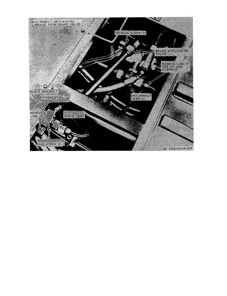
Figure 5-9. Differential pressure switch and brake valve, removal and installation. |
|
||
| ||||||||||
|
|
 TM 10-3930-242-34
removal and installation.
at maximum when the brake valve piston is
plunger (13) with the edge of the seal toward the
completely depressed. Maximum pressure at
v a l v e seat (22). Install the plunger.
t h e valve is controlled by shims assembled be-
(25) Install the washer (12).
n e a t h the operating piston. Add shims to in-
(26) Install the snap ring (11) and engage it
c r e a s e pressure, remove shims to decrease pres-
i n the groove about the washer.
sure. Use a 0-2,000 pounds-per-square-inch (psi)
(27) Install the O-ring (10).
g a g e to test the valve.
(28) Install the shims (7 and 8) and spring (9)
(a) Screw gage into brake port on valve.
in the piston (6) and push it into the valve body.
(29) Make sure the piston is operating freely,
(b) Fill pump with hydraulic oil, and at-
a n d then slowly release it. Check the clearance
t a c h it to accumulator port on valve.
under the flange of the piston. If new parts have
(c) Pump up valve to 1,900 psi,
been used, it may be necessary to either add or
(d) Remove boot (5) and depress operating
s u b t r a c t shims (7 and 8) from inside the piston
piston (6) all the way in and read gage. The
( 6 ) in order to get the proper clearance at this
c o r r e c t brake line pressure should read 225-275
point. Proper clearance is from 0.199-0.211 inch.
psi.
(30) Install the boot (5) and ring (4).
( 2 ) Accumulator pressure is the pressure of
e. Test Procedure.
(1) Before the brake valve is installed in the
the oil in the accumulator used for applying the
brakes. The maximum accumulator or high
forklift, gage test it on work bench to insure
l i m i t pressure is controlled by the pilot valve
t h a t it is properly assembled. Brake pressure is
spring. This is purposefully set below the steer-
t h e regulated accumulator pressure allowed to
ing relief valve for safety reasons, otherwise the
pass through the valve to apply the brakes. It is
|
|
Privacy Statement - Press Release - Copyright Information. - Contact Us |