 |
|||
|
|
|||
|
Page Title:
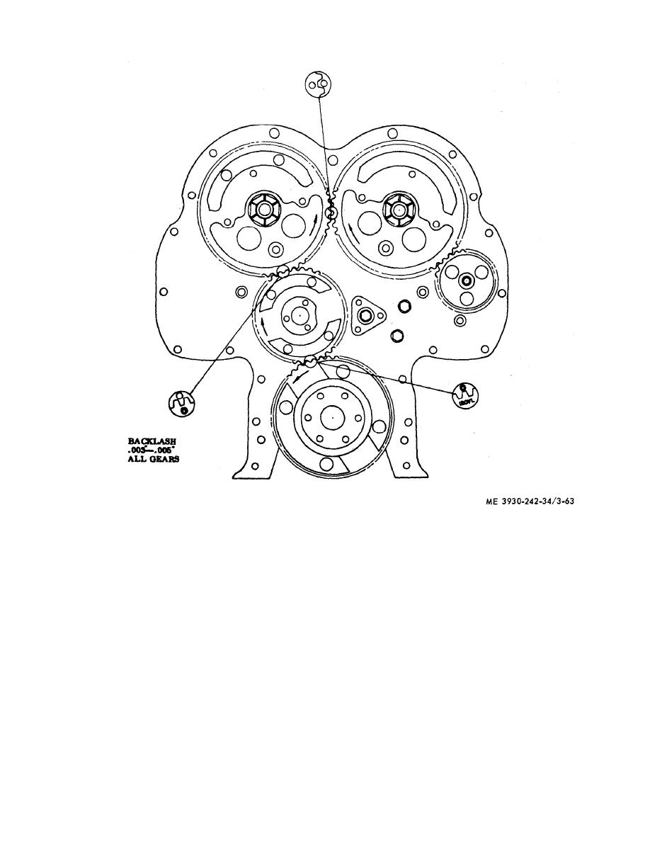
Figure 3-63. Gear train and timing marks. |
|
||
| ||||||||||
|
|
 TM 10-3930-242-34
(10) Scribe a line on the crankshaft pulley in
NOTE
line with the end of the pointer.
The mounting leg may be threaded into the rocker
cover retaining screw hole on the injector rack side
(11) Turn the crankshaft the opposite the di-
o f the cylinder head. Make sure that the spindle
r e c t i o n of rotation slowly until the hand on the
extension is free in the injector hole, does not bind,
and is free to travel its full 1 inch movement,
d i a l indicator just stops moving.
(7) Provide a suitable pointer and attach it
( 1 2 ) Turn the crankshaft opposite the direc-
t o the lower engine front cover. The pointer
t i o n of rotation until the indicator hand just
s h o u l d extend over the crankshaft pulley.
s t a r t s to move. Reset the dial to "0". Continue
( 8 ) Turn the crankshaft in the direction of
barring slowly until indicator reading is
rotation, slowly, until the hand on the dial indi-
0.010-then stop turning.
a t o r just stops moving.
( 1 3 ) Scribe a second line on the crankshaft
( 9 ) Turn the crankshaft in the direction of
pulley in the same manner, as in step 10.
r o t a t i o n until the indicator hand just starts to
( 1 4 ) Scribe a third line halfway between the
m o v e . Reset the dial to "0". Continue barring
f i r s t two lines. This is positive top-dead-center.
slowly until indicator reading is 0.010-then
R e m o v e the indicator from the engine.
stop turning.
|
|
Privacy Statement - Press Release - Copyright Information. - Contact Us |