 |
|||
|
|
|||
|
|
|||
| ||||||||||
|
|
 TM10-3930-242-12
slack adjusters and remove as follows:
(1) Tag and disconnect two hydraulic lines to
each slack adjuster.
(2) Cap all lines when disconnected to prevent
foreign material from entering the brake system.
(3) Remove two screws, nuts, and lockwashers
attaching each slack adjuster to the main frame.
Remove the four slack adjusters.
b. Cleaning and Inspection
(1) Clean slack adjuster with an approved
cleaning solvent and dry thoroughly.
(2) Inspect for corrosion, cracks, and loose con-
nections. Check hoses for cuts and deterioration.
c. Installation. Refer to figure 4-37 and install
the slack adjusters as follows:
(1) Use two screws, nuts, and lockwashers to
mount each of the four slack adjusters to the main
frame.
(2) Reconnect two hydraulic lines to each of the
slack adjusters.
refer to paragraph 4-59b and bleed the hydraulic
brake system.
TA072400
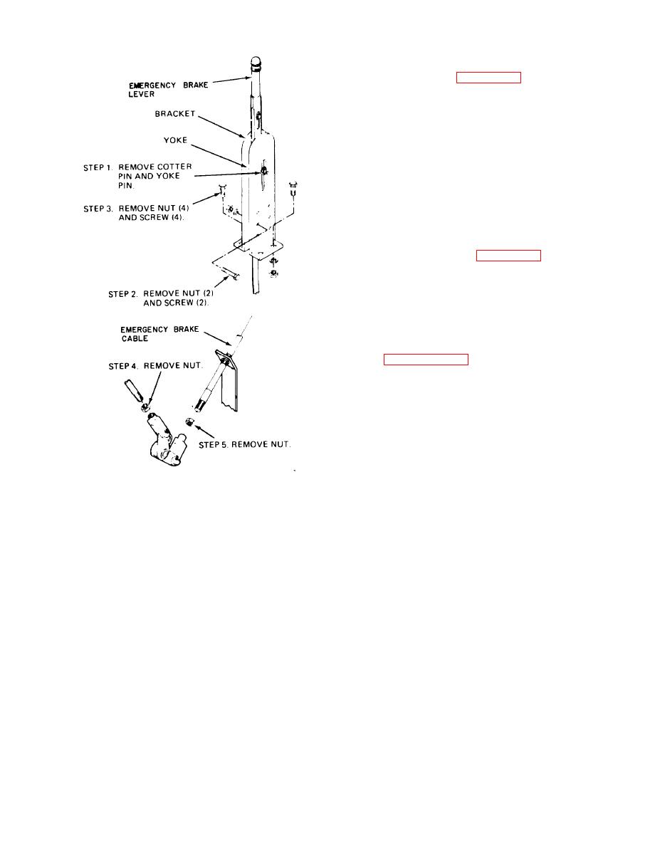
and installation.
|
|
Privacy Statement - Press Release - Copyright Information. - Contact Us |