 |
|||
|
|
|||
|
Page Title:
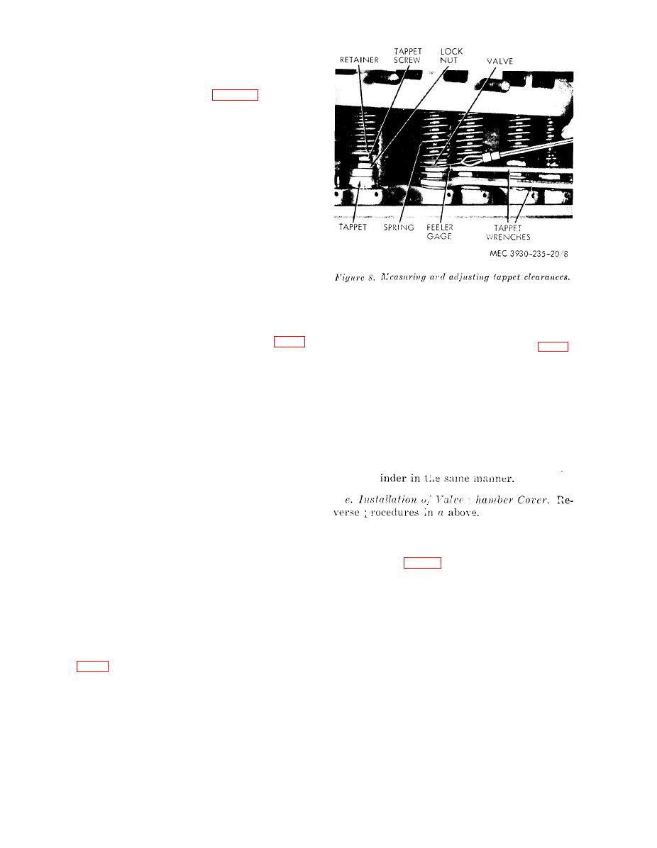
figure 8. measuring and adjusting tappet clearances |
|
||
| ||||||||||
|
|
 c. Installation.
(1) Reverse procedures in a above using a
new head gasket.
(2) Tighten the cylinder head nuts in the
sequence shown in figure 7 to a torque
value of 60 to 65 foot-pounds.
Note. Tighten nuts in the proper sequence
to about one-half the required torque value
for the first tightening. At the second tight-
ening bring torque value up to the required
foot-pounds.
(3) Start engine, inspect for leaks and
observe e n g i n e performance. Re-
tighten cylinder head nuts when en-
gine is hot.
22. Valves
Correct valve clearance settings prolong en-
gine life and aid performance. Excessive clear-
ances will disturb timing and will harm cam-
shaft and tappets. Insufficient clearances will
compression stroke. Both valves of
also disturb timing and possibly cause burned
No. 1 cylinder will be closed at this
valves. Correct valve clearance for both intake
position.
and exhaust valves is 0.014 inch hot (fig. 8).
(2) With a 0.014-inch feeler gage (fig. 8)
check clearance between adjusting
a. Removal of Valve Chamber Covers (figs.
screw and roto cap on each va!ve.
8 and 10).
(3) To adjust each valve to proper clear-
(1) Disconnect air cleaner hose from air
ance of 0.014 inch hot, hold the valve
cleaner and carburetor.
lifter assembly firmly with wrench,
(2) Disconnect choke cable and throttle
arid with another wrench, turn adjust-
linkage at carburetor.
ing screw until desired clearance is
(3) Disconnect fuel line at carburetor.
obtained.
(4) Remove two mounting nuts and wash-
(4) Adjust remaining valves for each cyl-
ers, then remove carburetor and
gasket.
(5) Remove two barrel nuts and gaskets,
then remove valve cover and valve
cover gasket. Remove baffles.
22. Intake and Exhaust Manifold
b. Cleaning of Valve Chamber Cover. Clean
cover with SD. Use new gasket when installing
cover.
(1) Connect air cleaner hose from car-
buretor.
c. Inspection of Valve Springs, Locks, and
Seats. Inspect valve springs, locks, and seats
(2) Disconnect choke cable and throttle
for alignment, for cracks, and proper seating.
linkage from carburetor.
Check for weak springs.
(3) Disconnect fuel line at carburetor.
d. Adjustment of Intake and Exhaust Valves
(4) Remove mounting nuts and washers,
then remove carburetor and gasket.
(1) Remove spark plugs and rotate engine
(5) Loosen clamp that attaches muffler to
until No. 1 piston is at TDC on its
frame.
AGO 6217A
|
|
Privacy Statement - Press Release - Copyright Information. - Contact Us |