 |
|||
|
|
|||
|
Page Title:
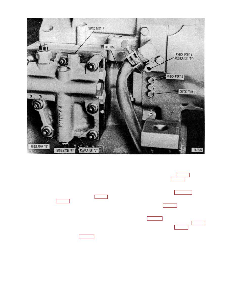
Figure 29. Left side view of transmission and control valve, showing oil check ports. |
|
||
| ||||||||||
|
|
 Figure 29. Left side view of transmission and control valve, showing oil check ports.
(9) Install first separator plate so springs will rest on
(4) Install reverse gear assembly (18) through end
lugs of separator plate (fig. 42).
housing assembly (22) and then install clutch
(10) Install friction disk (fig. 44); then in-tall inner
hub (27) on reverse gear assembly (18).
spring into outer spring. Install assembled
(5) Install retaining rings (26 and 28) on gear
springs on lugs of first separator plate in
assembly (18).
alinement according to figure 45.
(6) Place housing assembly on suitable jig to permit
(11) Install second separator plate with lugs indexed
ease of reassembly of clutch assembly (fig. 41).
to allow mating of springs which rest on the first
(7) Place clutch ring (fig. 42) on housing.
separator plate (fig. 45).
(8) Install four capscrews through clutch ring and
(12) Install separator plates and friction disks
clutch end to assure proper alinement of
alternately until all separator plates and friction
retainer bolt holes.
disks (fig. 46) are installed. The long dots on
Note. All separator plates are "dished".
the friction disks must be alined (fig. 47).
Install separator plates so that "dished" side
(13) Install thrust washer (fig. 48), teeth side down
is faced upward. To check for "dishing" of
on the forward gear. The
separator plate, lay the plate on smooth
surface and use feeler gage (fig. 48).
AGO 7010A
43
|
|
Privacy Statement - Press Release - Copyright Information. - Contact Us |