 |
|||
|
|
|||
|
Page Title:
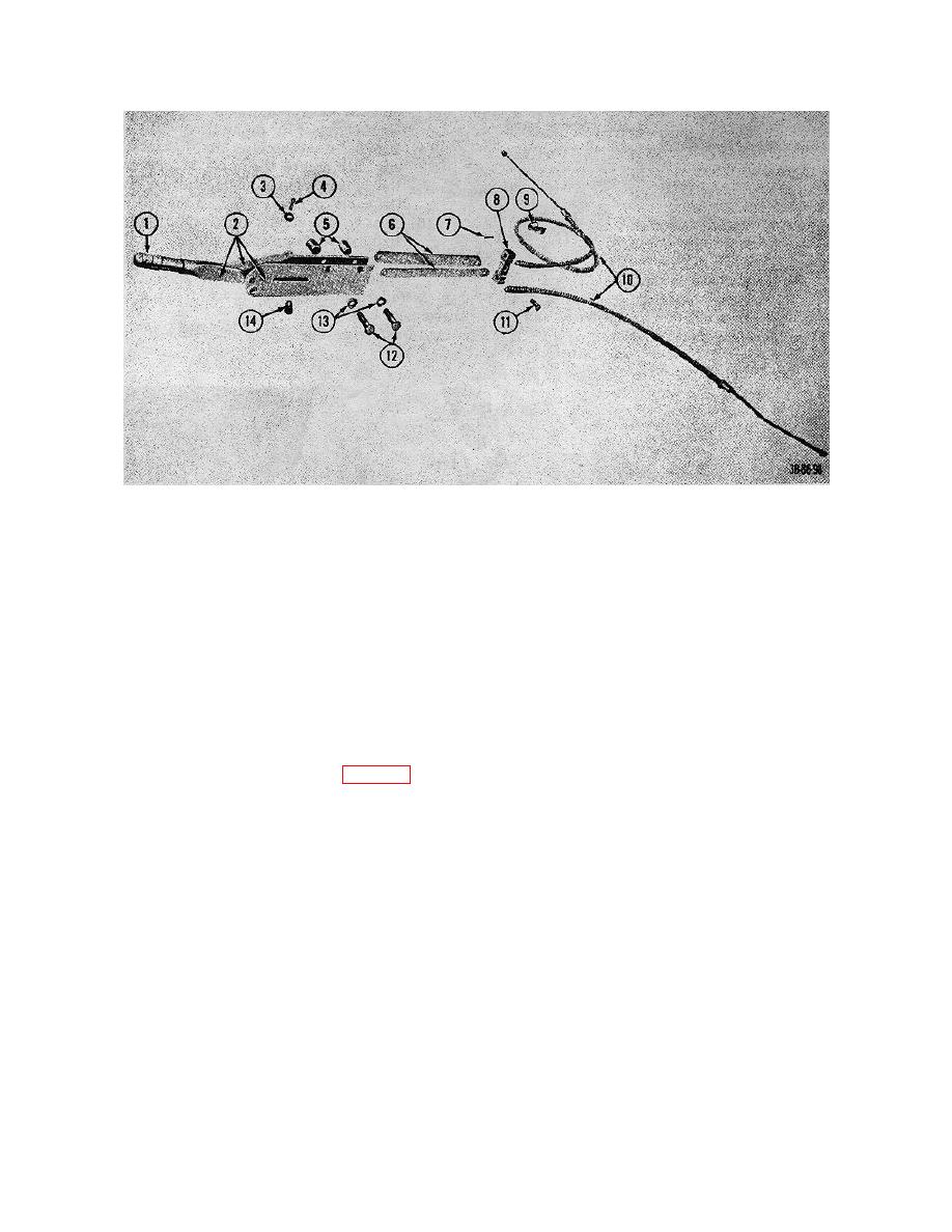
Figure 71. Handbrake and linkage, exploded view. |
|
||
| ||||||||||
|
|
 TM 10-3930-222-20
1
Knob
8
Bar, equalizer
2
Lever, handbrake
9
Clamp, cable
3
Washer
10
Cables, handbrake
4
Pin, cotter
11
Pin, rod end
5
Spacers
12
Capscrews.
6
Links
13
Lockwashers
7
Pin, cotter
14
Pin
Figure 71. Handbrake and linkage, exploded view.
63. Brake and Inching Controls
the brake and inching controls to the truck
and remove the brake and inching
controls.
a. Removal.
(7) Place the special Hyster wrench on the
(1) Remove the floor plates.
slot of the inching spool of the
(2) Remove the cotter pin (5, fig. 72) and
transmission control valve.
Hold the
clevis pin (9) and disconnect the clevis (8)
inching spool firmly and unscrew the ball
and master cylinder push rod (7) from the
joint (48) from the inching spool.
brake pedal assembly (22).
(8) Remove the lockwasher (49) and special
(3) Remove the nut (38) and lockwasher (40)
washer (50) from the ball joint.
that secure the inching pedal. linkage to
(9) Remove the inching pedal linkage.
the inching lever (33) and separate the
linkage from the inching lever.
b. Disassembly.
(4) Disconnect and remove the brake pedal
return spring (21).
(1) Unscrew and remove the pedal pads (1
and 3) and lockwashers (2 and 4) from the
(5) Disconnect and remove the inching pedal
inching pedal assembly (28) and the
return spring (18).
brake pedal assembly (22).
(6) Remove the capscrews (15) and
(2) Remove the right-hand bracket (12) from
lockwashers (14) that secure each end of
the cross-shaft (26).
114
|
|
Privacy Statement - Press Release - Copyright Information. - Contact Us |