 |
|||
|
|
|||
|
Page Title:
Figure 44. Adjusting cutout relay armature airgap. |
|
||
| ||||||||||
|
|
 TM 10-3930-222-20
(2) Remove the cap assembly (4) from the
distributor.
a. Removal.
(3) Loosen the pins (fig. 57) on the inside of
(1) Disconnect the lead assemblies (2, fig.
the cap assembly and remove the high
tension leads from the cap assembly.
(2) Disconnect the primary lead wire at
(4) Remove the rotor (5, fig. 56) and housing
distributor.
cover (6) from the distributor.
(3) Loosen the bolt (13) on the clamp
(5) Remove the terminal nut (fig. 58).
assembly (12)
and remove the
(6) Remove the lock screw (fig. 58).
distributor. (The distributor drive shaft is
offset.)
(7) Remove the contact set and terminal (fig.
58).
(4) Remove the nut and lockwasher that
secure the adapter (14) to the cylinder
(8) Remove the screw and lockwasher that
head and remove the adapter.
secure the capacitor to the distributor and
remove the capacitor (fig. 58).
b. Disassembly.
c. Assembly. Reverse procedures in b above.
(1) Remove the capscrew (16, fig. 56) and
lockwasher (15) that secure the clamp
d. Installation. Reverse procedures in a above.
assembly to the adapter (14) and remove
the clamp assembly.
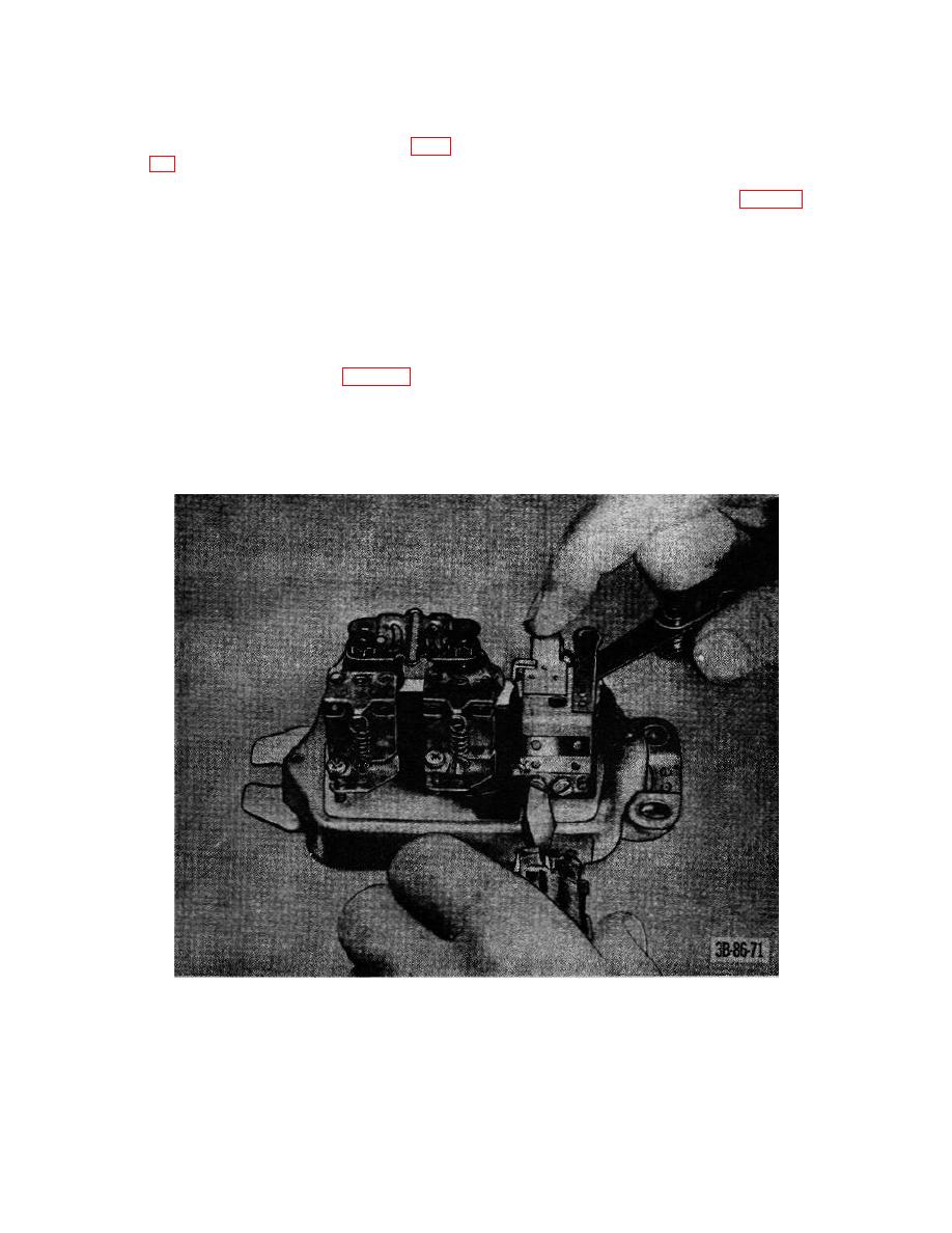
Figure 44. Adjusting cutout relay armature airgap.
85
|
|
Privacy Statement - Press Release - Copyright Information. - Contact Us |