 |
|||
|
|
|||
|
Page Title:
Figure 21. Governor installed on truck. |
|
||
| ||||||||||
|
|
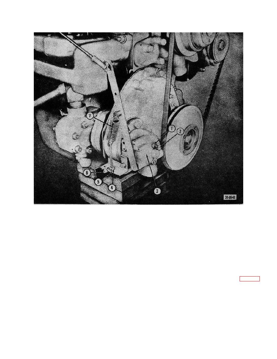 TM 10-3930-222-20
1
Nut
5 Nut, adjusting
2
Bolt, surge adjusting
6 Wire, seal
3
Governor
7 Spring
4
Nut
Figure 21. Governor installed on truck.
30. Fuel Tank
(3) Run the engine at 500 revolutions per
minute on the fuel remaining in the
a. Removal.
carburetor.
(1) Remove the floor panels and seat support
(4) The reading on the gage is the static
from the truck.
pressure of the fuel pump, and this
(2) Drain the fuel from the tank.
reading should be 3 pounds per square
(3) Remove the cap assembly (1, fig. 25)
inch, which is maximum. The length of
from the tank (18).
hose on the pressure gage should not
(4) Disconnect the fuel gage wire (5, fig, 26)
exceed 6 inches, since inaccurate
at tank.
readings may result if longer hose is used
(5) Unscrew and disconnect the line
between the pump fitting and gage.
assembly (1) at the shutoff valve.
62
|
|
Privacy Statement - Press Release - Copyright Information. - Contact Us |
