 |
|||
|
|
|||
|
Page Title:
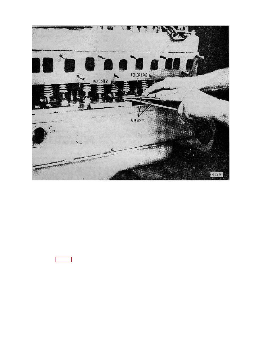
Figure 19. Adjusting the valves. |
|
||
| ||||||||||
|
|
 TM 10-3930-222-20
Figure 19. Adjusting the valves.
Section V. FUEL SYSTEM (GROUP 03)
25. General
(3) Disconnect the choke control linkage (2)
at the carburetor.
The fuel system consists of a fuel tank, a mechanical
(4) Disconnect the governor control linkage
fuel pump, a fuel gage sending unit, a carburetor oil
(4) at the.
bath air cleaner, a down-draft carburetor, and a
(5) Disconnect the accelerator control linkage
centrifugal ball-type governor.
(6) at the carburetor.
(6) Remove the nuts and lockwashers that
26. Carburetor
secure the carburetor and remove the
a. Removal.
carburetor and gasket.
(1) Disconnect the fuel line at the carburetor.
(7) Remove the studs from the manifold if
(2) Disconnect and separate the air cleaner
necessary.
hose (1, fig. 20) from the carburetor.
b. Installation. Reverse procedures in a above,
using a new gasket.
59
|
|
Privacy Statement - Press Release - Copyright Information. - Contact Us |