 |
|||
|
|
|||
|
|
|||
| ||||||||||
|
|
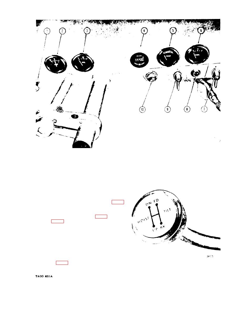 1
Choke control
6
Fuel gage
2
7
Light switch
8
Converter oil temperature warning light
3
Oil pressure gage
4
Hour meter
9
Ignition switch
5
Water temperature gage
10
Starter switch
Figure 4. Instrument panel.
the ignition system. The ignition switch must
be turned to the OFF position when the truck
is not in use.
is located on the extreme right side of the
instrument panel. Turn the light switch to the
right to turn on the headlight (fig. 1) and the
taillight (fig. 2).
n. Seat Adjuster Assembly. An adjuster as-
sembly is located under the operator's seat.
Move the adjuster lever to the right, adjust the
seat forward or backward as desired, and re-
lease the adjuster lever to secure the adjust-
ment.
o. Fork Adjusting Crank. The fork adjust-
ing crank (fig. 1) is located on the left side of
Figure 5. Hydraulic control lever.
the fork carriage. Turn the crank clockwise to
9
|
|
Privacy Statement - Press Release - Copyright Information. - Contact Us |
