 |
|||
|
|
|||
|
|
|||
| ||||||||||
|
|
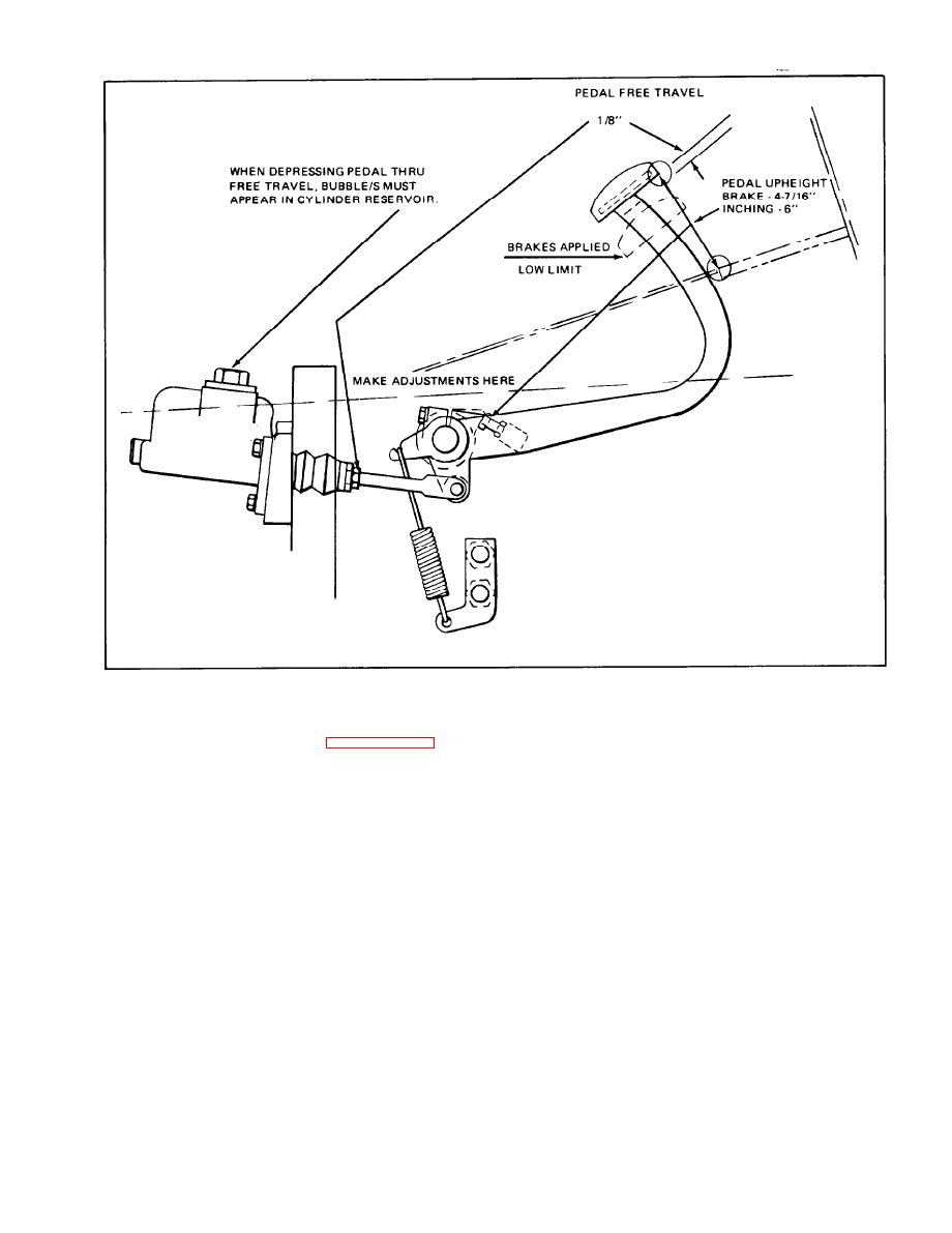 Figure 4-30. Pedal Adjustments
Pedal up-height must conform to
e.
Check the master cylinder filler
b.
the dimensions shown in figure 4-30.
cap vent hole.
This vent must be open
Adjustment is made at the stop screw
at all times, to allow proper fluid
shown in the illustration.
movement within the master cylinder. If
necessary, use a fine wire or small drill
If pedal travel exceeds the
f.
to clear the vent of any obstruction.
approximate "low limit" shown in the
See Figure 4-31 for vent location.
illustration, brake fluid is low, air
is trapped in the brake system, or
C.
Always make certain that pedal
brake linings are worn and require
adjustments are properly made, as im-
replacement.
proper pedal up-height will cause the
internal porting in the master cylinder
4-18.
MASTER CYLINDER CHECKS. The
to be blocked so that fluid will be
master cylinder should be checked
trapped, under pressure, in the brake
whenever pedal travel adjustments are
This fluid can hold the linings
lines.
Proceed as follows:
made.
in constant contact with the drums,
Check the fluid level within
a.
causing excessive lining wear and fuel
the master cylinder,
The fluid level
consumption.
should be within 1/4 inch from the
top of the filler neck.
Use only
SAE 70 R3 Heavy Duty Hydraulic Brake
Fluid, when adding fluid.
4-21
|
|
Privacy Statement - Press Release - Copyright Information. - Contact Us |
