 |
|||
|
|
|||
|
|
|||
| ||||||||||
|
|
 TM 10-3930-644-14&P
D. INSPECTION
1. When the pump is removed, examine the drive
gear carefully for wear, inspecting the gear on
the camshaft at the same time. If scored or
worn badly, both the camshaft and the gear on
the pump must be replaced.
2. Examine the pick-u p screen for clogging or
damage.
3. Remove the cover, being careful not to damage
the lead gasket which acts as a spacer as well
as a gasket to seal the joint.
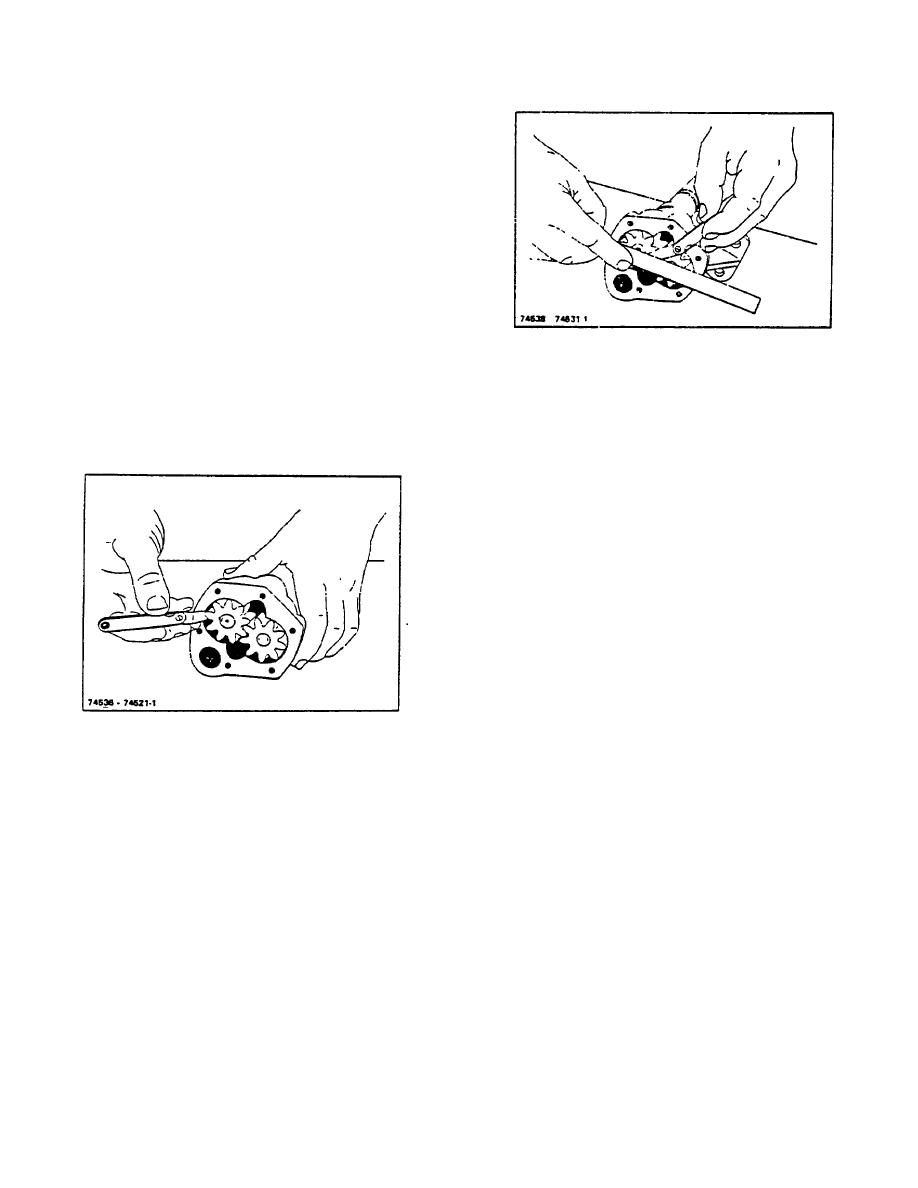
Figure 12-4. Checking Oil Pump End Clearance
4. Examine the gears and pump body for any sign
of wear indicating lack of clearance. The gears
E. ASSEMBLY
should have from .001" to .003" clearance in the
chamber and should make no contact with the
Press drive gear on its shaft and install shaft in pump
walls (Figure 12-3).
body. Secure with snap ring. Press spiral gear back on
end of drive shaft and replace retainer pin. Replace idler
gear, if it was removed, and install oil pump cover and
gasket. Install spacer, frame and screen.
F. INSTALLATION
1. Re-install oil pump assembly on center main
bearing cap. Carefully manipulate the pump
assembly to allow the spiral gear to mesh with
the camshaft mating gear, and with the bushing
connecting to the distributor drive. Make sure
the oil pump assembly is properly seated on the
center, main bearing cap, and secure with
lockwasher and nut.
2. Install oil pan with new oil pan gaskets. Secure
oil pan with attaching capscrews and make sure
Figure 12-3. Checking Oil Pump Gear Clearance in
drain plug is installed.
Pump Body
3. Install engine in truck (refer to TOPIC 17.
5. Inspect the cover and face of the gears for
ENGINE REMOVAL/INSTALLATION.
excessive wear or scoring. With the gasket
assembled to the body there should be .0015" to
4. Upon complete re-assembly, ensure that proper
.006" clearance between the gears and the
weight and quantity of oil have been soured into
cover (Figure 12-4).
crankcase, refer to Maintenance Module
LUBRICANT AND FUEL SPECIFICATIONS
6. Worn or scored gears can be replaced, as can a
worn cover. If the body shows wear in the
5. Start engine, check for oil leaks.
chamber, it can be replaced; but, in a case like
this, a new pump would be the most economical.
6. Refer to TOPIC 13. OIL PRESSURE RELIEF
VALVE ADJUSTMENT to verify proper oil
7. Engine oil pressure must be maintained to
pressure setting.
specification for satisfactory engine life.
7. Turn engine off.
R-104-1
3-44
|
|
Privacy Statement - Press Release - Copyright Information. - Contact Us |
