 |
|||
|
|
|||
|
Page Title:
TOPIC 13. OIL PRESSURE RELIEF VALVE |
|
||
| ||||||||||
|
|
 TM 10-3930-644-14&P
TOPIC 13. OIL PRESSURE RELIEF VALVE
A. DESCRIPTION
gauge and its connections before going any
farther.
Stabilized lubricating oil pressure is maintained within
the engine at all speeds, regardless of oil temperature,
4. A common source of low oil pressure is clogging
by means of the oil pressure relief valve. This valve is
of the oil pump intake screen with sludge and
located on the left side of the engine, directly below the
carbon. Remove such deposits with a solvent.
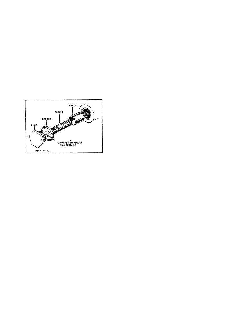
carburetor (Figure 11-1). The valve assembly consists
of a plunger, compression spring, adjusting washer or
5. Unusual looseness, grooving, or damage to the
washers, copper gasket, and a plug screwed on the
camshaft bearings or oil pump will also cause
crankcase valve opening (Figure 13-1).
When oil
low oil pressure.
Such conditions call for
pressure at the valve exceeds the 30-40 P.S.I. limit, the
replacement of worn parts.
plunger is lifted off its seat, and oil from the main gallery
is by-passed to the engine oil pan.
D. INSPECTION
Clean oil pressure relief valve parts with a solvent and
dry with compressed air. Replace the spring if it is worn,
bent out of shape, cracked, or weak. Replace cooper
gasket to form an oil tight seal.
E. ADJUSTMENT
The only adjustment variation is, either to install a new
compression spring, or to assemble or remove washers
from behind the existing spring. Up to four washers can
be assembled.
Whenever a relief valve adjustment is necessary, it
should be done AFTER the engine and oil have reached
normal operating temperatures. It is equally important
Figure 13-1. Oil Pressure Relief Valve Assembly
that all other factors such as grade and condition of oil,
bearing clearances, and security of line connections be
B. REMOVAL
satisfactory before any adjustment is attempted.
Proceed as follows:
Under normal conditions, the valve requires very little
attention. However, if the lubricating system has been
1. Allow engine to run until oil reaches normal
allowed to sludge up, the regulator valve may not work
operating temperature.
freely, thereby remaining open or closed. Whenever the
lubricating oil puma is removed for repairs or inspection,
2. Check oil pressure at oil pressure gauge on
the regulator valve should also be disassembled,
instrument panel; verify adjustment using
thoroughly cleaned, and parts inspected.
calibrated oil pressure gauge.
C. DISASSEMBLY
a. Recommended pressure with engine hot
at an idle is 5 to 10 P.S.I.
If, with the proper grade of oil, and the engine warmed
up and running at normal governed speed, and after
b. Recommended pressure with engine hot
adjusting the relief valve the oil pressure is unusually
at full throttle is 30 to 40 P.S.I.
high or low, the following corrective measures should be
tried:
3. To increase pressure, assemble washers one by
one. If after assembling four washers pressure
1. Remove and clean relief valve parts of dirt,
is still low, replace compression spring.
sludge, or carbon.
4. To decrease pressure remove the existing
2. Check oil temperature and condition of oil.
washers, one by one. If pressure is still high,
replace compression spring.
3. If both the relief valve and oil are in good
condition, be sure to check the oil pressure
5. After adjustment is completed, install a new
copper gasket, install and tighten plug.
R-104-1
3-45
|
|
Privacy Statement - Press Release - Copyright Information. - Contact Us |
