 |
|||
|
|
|||
|
|
|||
| ||||||||||
|
|
 TM 10-3930-644-14&P
TOPIC 12. OIL PUMP
A. DESCRIPTION
B. REMOVAL
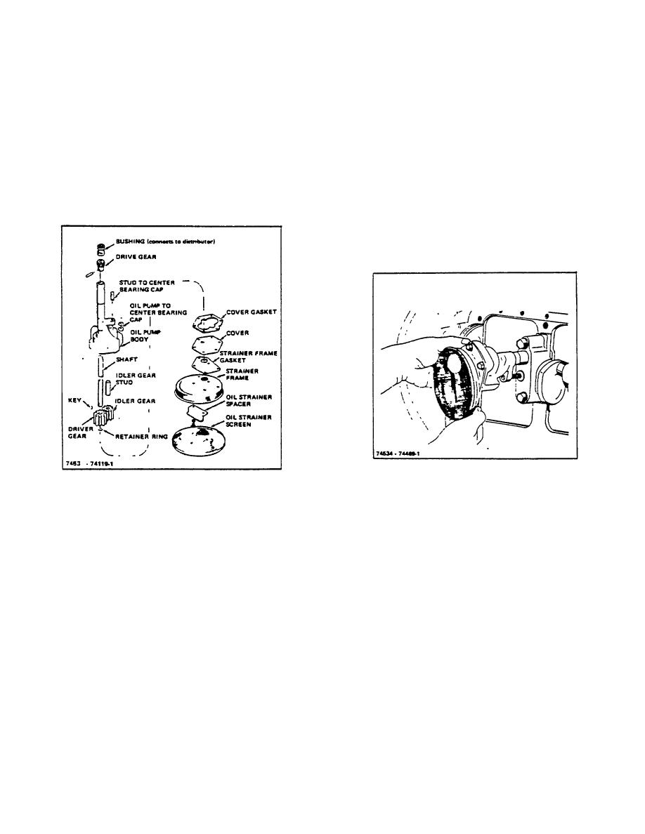
The lubricating oil pump (Figure 12-1) is a positive, gear
1. Refer to TOPIC 17.
ENGINE REMOVAL/
type assembly. It consists of a single cast pump housing
INSTALLATION.
and mounting extension with a precision cavity to
receive the driver and idler gears. The driver gear is
2. Drain oil pan, and remove the capscrews
mounted at the end of the pump shaft, and the idler gear
securing the oil pan. Remove the oil pan and its
is mounted on a stud which is pressed in place in the
gasket.
pump body.
3. With the engine resting on its side, remove nut
and washer holding the oil pump assembly to
the center main bearing cap. Remove the oil
pump assembly (Figure 12-2).
Figure 12-2. Oil Pump Removal
Figure 12-1. 011 Pump, Exploded View
C. DISASSEMBLY
The oil pump is assembled to the center main bearing
cap held in position vertically against a machined pad by
1. Remove screen and remove screws securing
studs.
frame and cover to pump body. Remove spacer
and frame.
The extended portion of the pump body acts as a pilot,
fitting closely in a reamed hole in the main bearing web,
2. Remove oil pump cover and gasket.
maintaining definite relationship between the camshaft
and the oil pump drive shaft.
3. Support spiral gear at the upper end of pump on
a wood block and drive out retaining pin with a
A gear assembled to the upper end of the drive shaft is
drift. Press shaft out of spiral gear and remove
driven by a mating gear cut on the camshaft. The
shaft and drive gear from pump body.
mating gear drives the oil pump gear which is assembled
to the lower end of the pump shaft.
4. Remove retainer ring from drive gear end of
shaft and place shaft on suitable support in an
The pump shaft is carried in two bronze bushings
arbor press. Remove gear from shaft.
assembled in the cast iron housing, which is also a part
of the oil distributing system. transmitting oil to the
5. Remove idler gear from stud.
drilled passages.
6. Clean all parts in an acceptable solvent and dry
R-104-1
with compressed air.
3-43
|
|
Privacy Statement - Press Release - Copyright Information. - Contact Us |
