 |
|||
|
|
|||
|
|
|||
| ||||||||||
|
|
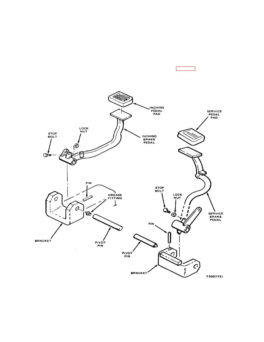 TM 10-3930-632-12
paragraph 4-75d., after filling master cylinders with
measure the distance from inside the front cowl to the
farthest edge of the service and inching brake pedals.
brake fluid. After bleeding, apply and hold the brakes
These should be:
firmly and check for leaks around connections.
Service brake pedal 9 3/8 to 9 5/8 in.
4-78. Brake Pedal and Linkage
Inching brake pedal 8 5/8 to 8 3/4 in.
NOTE
a. Adjustment. Brake and inching pedals and
The maximum pedal "UP" position is adjusted
linkage must be adjusted to provide 1/8 to 1/4 inch free
by means of stop screws which bear against the
play. This adjustment is made in two steps. Proceed as
pedal brackets (fig. 4-58).
follows:
(1) Remove floor plates to expose pedal
arms, linkage, and master cylinders. Using a ruler
Figure 4-58. Brake Pedal and Linkage, Adjustment
Change 1 4-74
|
|
Privacy Statement - Press Release - Copyright Information. - Contact Us |
