 |
|||
|
|
|||
|
Page Title:
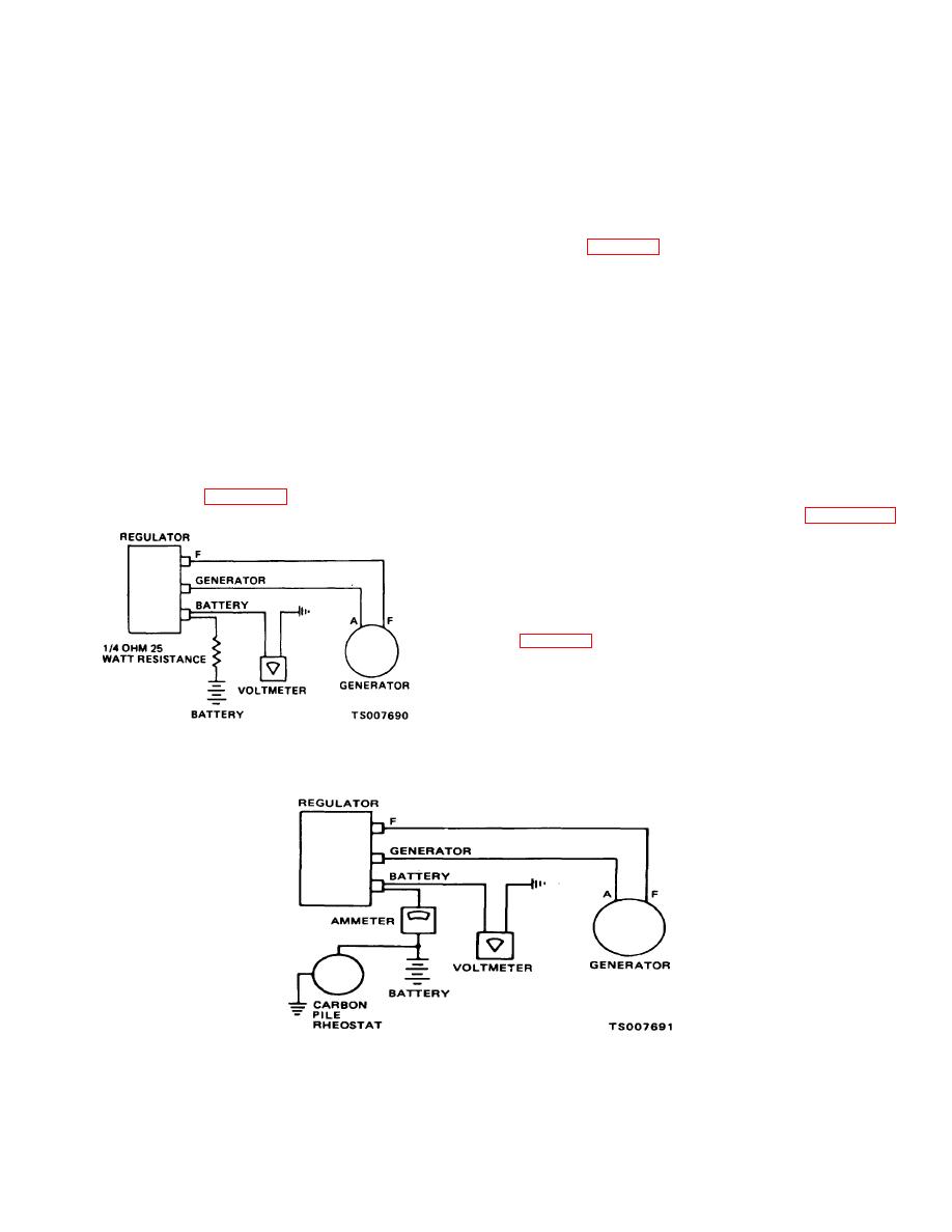
Test and adjust the current regulator as |
|
||
| ||||||||||
|
|
 TM 10-3930-632-12
CAUTION
(b) Gradually increase the speed of
the alternator until the relay contacts close. Note the
Make sure the ends of the leads are
voltage; it should be between 11.8 and 13.5 volts. If the
insulated from the ground at all times to
closing voltage is not within this range, adjust by turning
avoid a short circuit.
the adjusting screw on top of the cutout relay.
(b) Cycle the alternator as directed in
CAUTION
subparagraph (3). With the alternator operating at 4000
Cycle the alternator before each test and
RPM and the regulator at operating temperature, note
adjustment by reducing the alternator speed
the voltage registered on the voltmeter; it should be as
until the cutout relay opens; then increase
indicated in table 4-3. If the voltage is not within this
the speed slowly until the proper speed for
range, adjust by turning the adjusting screw at the back
testing is reached.
of the voltage regulator. Cycle the alternator after each
(4) Test and adjust the voltage regulator
change or adjustment.
as follows:
(5) Test and adjust the current regulator as
(a) Measure the voltage regulator
follows:
airgap. Push the armature down until the points open;
(a) Measure the airgap of the current
release until the points barely close. Measure the airgap
regulator by the same method used to measure the
at the point between the armature and the part of the
airgap of the voltage regulator in subparagraph (4) (a).
core next to the residual pin. The airgap should be
This airgap between the armature and that part of the
0.075 inch. Adjust by loosening the contact mounting
core next to the residual pin should be 0.075 inch.
screws, inserting a 0.075-inch thick flat gage in the
Adjust the airgap by loosening the contact mounting
airgap. Position the contacts so they barely touch;
screws and positioning the contact. Tighten the screws
secure the contact mounting screws. Connect the
after the proper setting is obtained.
regulator as shown in figure 4-17.
(b) Test the current regulator setting
by connecting the regulator as shown in figure 4-18.
Prevent voltage regulator from operating during the test
by connecting a carbon pile load of approximately the
same value as the current regulator setting across the
battery terminals during the time the current regulator
setting test is made. When the alternator output is
increased to maximum, the current should be as shown
in table 4-3. If the amperage is not within this range,
adjust by rotating screw at the back of the current
regulator. After each change of adjustment, reduce the
alternator speed until the cutout relay opens; then return
to speed and check the current indication on the
Figure 4-17. Voltage Regulator Setting Test Circuit
Figure 4-18. Current Regulator Setting Test Circuit
4-33
|
|
Privacy Statement - Press Release - Copyright Information. - Contact Us |
