 |
|||
|
|
|||
|
Page Title:
Table 4-3. Temperature-Voltage and Temperature-Current Chart for Adjusting Voltage Regulator |
|
||
| ||||||||||
|
|
 TM 10-3930-632-12
Table 4-3. Temperature-Voltage and Temperature-Current Chart for Adjusting Voltage Regulator
Ambient temperature of regulator
65
85
105
125
145
165
185
(F.)
Voltage setting (volts) connect per
14.4-15.4
14.2-15.2
14.0-14.9
13.8-14.7
13.5-14.3
13.1-13.9
Current setting (amperes) connect per
25-30
24.5-20
23.5-28
23-27
21.5-25.5
20.5-24.5
19.5-23.5
CAUTION
WARNING
Dry cleaning solvent, P-D680, used to clean
Check airgap and point gap opening with
the battery disconnected.
parts is potentially dangerous to personnel
(3) Test and adjust the cutout relays as
and property.
Avoid repeated and
follows:
prolonged skin contact. Do not use near
(a) Measure the airgap of the cutout
open flame or excessive heat. Flash point
relay between the armature and the core with the
of solvent is 100F. -138F. (38C. -60C.).
contact points barely touching. The airgap should be
(2)
Clean the contact points of the
0.020 inch. If the points do not close, align the lower
regulator when they show signs of oxidation and pitting.
contact bracket slightly or bend the spring fingers on the
Oxidation of the contacts reduces the generator output.
armature until the points meet and align. Adjust the
Clean the thicker (tungsten) contact points with a riffler
airgap by loosening the two screws attaching the lower
file until the oxidation is removed. Clean the thinner
contact bracket. Raise or lower the contact bracket as
(platinum) contact with crocus cloth; wash with dry
required. Align the contact points and tighten the
cleaning solvent P-D-680 to remove any oily film. Blow
screws. Measure the contact point opening; it should be
the filings from the unit with compressed air to prevent
0.020 inch. Adjust to obtain the correct contact point
them from becoming embedded in the contact surfaces.
CAUTION
opening by bending the upper armature stop. To test
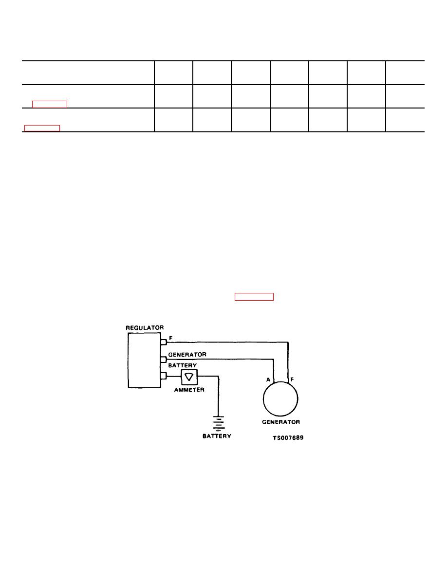
the closing voltage, connect the regulator as shown in
Do not file the contact points excessively.
Never use sandpaper or emery cloth. Use a
clean ignition file.
Figure 4-16. Cutout Relay Closing Voltage Test Circuit
CAUTION
voltage regulator. This will cause high
current to flow through the units and
Never close the cutout relay contact points
seriously damage them.
by hand with the battery connected to the
4-32
|
|
Privacy Statement - Press Release - Copyright Information. - Contact Us |
