 |
|||
|
|
|||
|
|
|||
| ||||||||||
|
|
 TM 10-3930-631-34
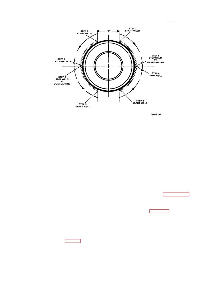
Figure 7-17. Bearing stud welding procedure.
Process ...........................
Shielded Metal Arc
disassembly. Secure upper bearings with screws (9).
Equipment .......................
Manual
(2) Install wear angles (17) and carriage frame.
Settings:
Install screws (4 and 6), lock washers (5) and spacer (7).
Current .........................
A.C.
(3) Install wear strip (16) on plate (23). Install
Amps .........................
275/325
lubrication fittings (13) in plate. Lubricate wear strips and
Volts ..........................
31/33
wear angles with a light coat of grease (GAA).
Base Metals.....................
(1) AC 1035-P-1
(4) Use a hoist and move assembled plate into
(2) AC 86L20H (roller stud)
position at right side of carriage frame. Carefully slide
Plate Thickness Range ... 3/8" - 1" (9.5 - 25.4 mm)
side shift plate into position on frame. Lift plate into
Electrode.
position over wear angles.
Type ............................. Stick
(5) Install lower hanger bar (15) and secure with
Class ............................ E 7018 (hydrogen free)
screws (14). Tighten screws to a torque of 28 to 33
Size .............................. 3/8" (9.5 mm)
pound feet (3.86-4.55 m-kg).
Flux .............................. Electrode Covering
(6) Lubricate all lubrication fittings (13) with
1
Weld Type and Size ........ /4" Fillet
grease (GAA).
e. Installation. Refer to paragraph 2-14 and install
Number of Passes ........... 1
Position............................ Horizontal
side shift carriage.
Preheat ............................ 400 degrees F (205C)
7-11. Side Shift Hoses
Interpass.......................... 250 degrees F (121C)
a. Removal.
(1) Refer to figure 7-18 and remove side shift
Postheat .......................... None
hoses from mast, reel and swivel block.
(e) When welding is completed, remove all slag,
(2) Remove screws and nuts as necessary to
weld spatter, and excessive weld material.
remove hoses.
(f) Remove the defective material with a small,
round grinder in 0.010-0.020 of an inch passes and
visually inspect for defects after each pass.
d. Assembly.
(1) Install bearings (10, fig. 7-15) and same
amount of shims (11 and 12) as were removed in
7-26
|
|
Privacy Statement - Press Release - Copyright Information. - Contact Us |
