 |
|||
|
|
|||
|
Page Title:
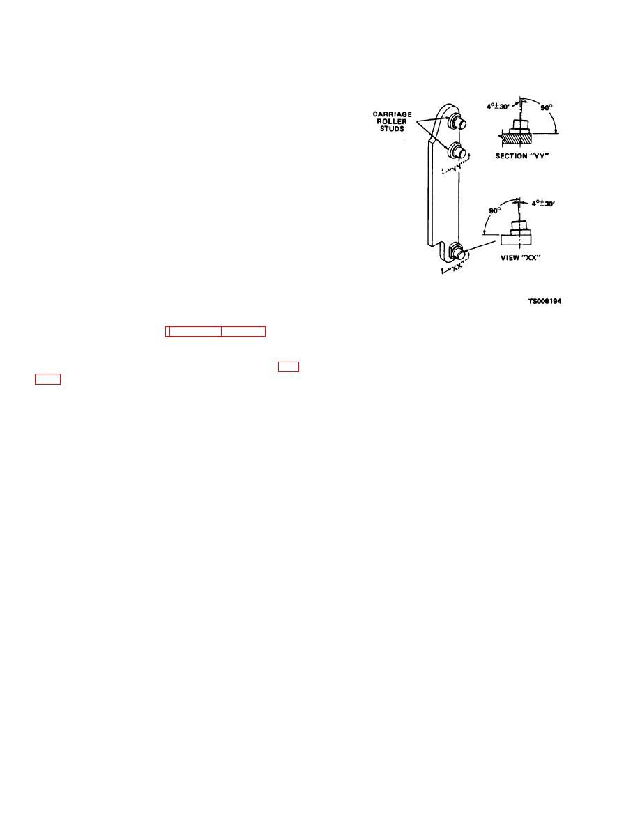
Figure 7-16. Carriage roller stud locations. |
|
||
| ||||||||||
|
|
 TM 10-3930-631-34
(2) Inspect all parts for cracks, broken welds
and other damage.
(3) Replace wear strips and wear angle if wear
surface has worn to a thickness of 0.063 inch (1.60 mm).
(4) Inspect bearings for wear and damage.
Inspect for cracked inner or outer races. Replace worn
or damaged bearings.
(5) Inspect bearings studs for wear and
damage. If studs are worn or damaged, remove studs
and weld new studs on supports as follows:
Note
The following procedures apply to carriage and
mast bearing studs.
(a) Remove the filler metal from around the stud
using a small, round grinder. Do not make any passes
into the mast channel or carriage supports. Remove the
stud from the channel or support.
(b) Prepare the welding surface by removing all
foreign material such as rust, scale, grease, etc. Any
part that may be damaged by heat should be removed
before welding.
(c) Locate, tilt and aline the new stud on mast
Figure 7-16. Carriage roller stud locations.
channel or support. Refer to figure 7-16 and 7-21 for
dimensions and stud locations.
(d) Comply with the following welding
specifications using bearing stud welding procedure (fig.
7-25
|
|
Privacy Statement - Press Release - Copyright Information. - Contact Us |
