 |
|||
|
|
|||
|
|
|||
| ||||||||||
|
|
 TM 10-3930-631-34
assembly on drive motor, using a new gasket (9, fig. 3-
(4) Refer to paragraph 2-10 and connect
8). Secure carrier with screws (5) and lock washers (6).
parking brake linkage and wires to drive motor.
Install bonding straps (8) under two of the screws.
(5) Refer to paragraph 3-8 to install axle shaft
(2) Install new gasket (15) on carrier. Move
and wheels.
carrier and drive motor under truck and lift into position
(6) Install drain plug and fill drive axle to proper
on drive axle.
level with specified oil (LO 10-3930-631-12).
(3) Install nuts (10) and lock washers (11) to
secure carrier and drive motor on drive axle.
Section III. WHEELS AND TIRES
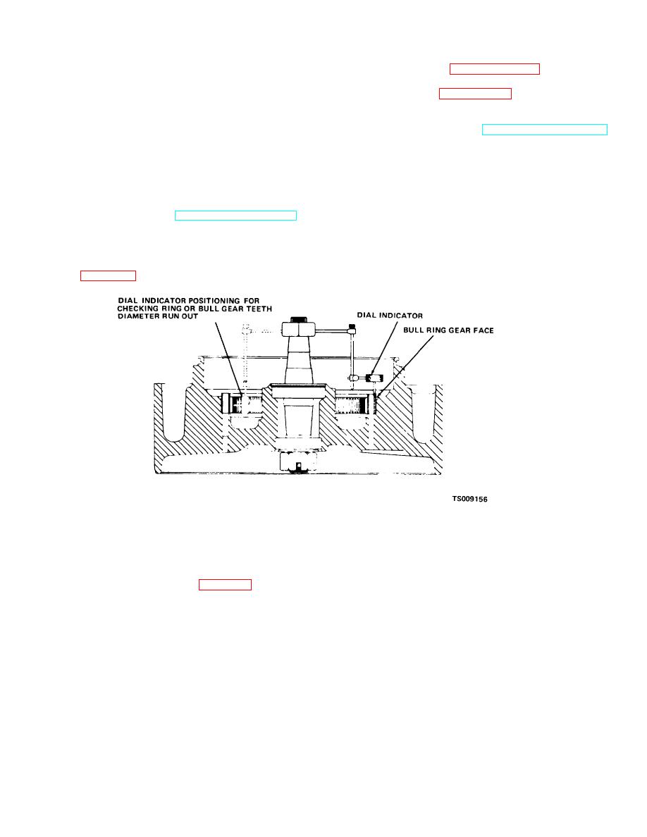
(3) Runout on gear face must not exceed .010
3-11. Drive Wheel
inch (.254 mm).
a. Removal.
Refer to TM 10-3930-631-12 to
(4) Maximum allowable runout on the inside
remove the drive wheel and bearings.
diameter is .005 inch (.127 mm).
(1) Before removal, check runout of ring or bull
(5) If runout exceeds these tolerances replace
gear face and inside diameter.
gear.
(2) Mount a dial indicator on the spindle as
shown in figure 3-15.
Figure 3-15. Checking ring or bull gear runout.
b. Disassembly.
(2) Turn wheel over and use screws inserted in
(1) Remove screws (9, fig. 3-16) and lock
holes in gear to remove gear from wheel. Tighten screws
washers (10) and remove ring or bull gear (11) from
alternately and evenly to remove 15 gear.
wheel (18).
3-15
|
|
Privacy Statement - Press Release - Copyright Information. - Contact Us |
