 |
|||
|
|
|||
|
Page Title:
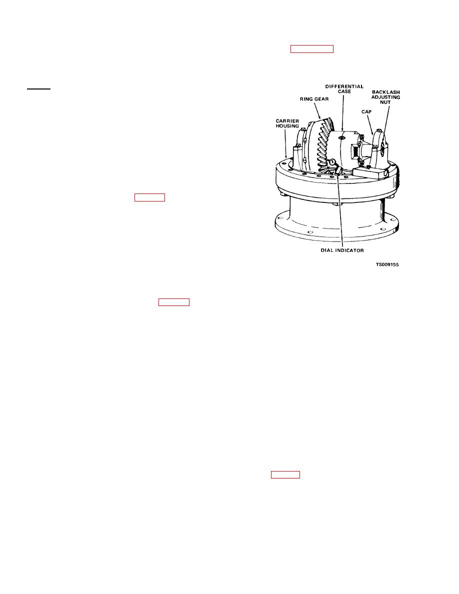
Figure 3-14. Adjusting backlash. |
|
||
| ||||||||||
|
|
 TM 10-3930-631-34
(15)If pinion is a minus .005 inches (etched
shown on figure 3-14. Backlash should be between
2.645) the .005 inches has been subtracted from the
.005 and .010 inch (0.127-0.254 mm).
theoretical setting therefore the amount of shims
required is found as follows:
2.715 total
-2.645,
.070 thickness of shims required
Note
The above dimensions are examples.
Use the exact one-half outside diameter
as measured plus the distance measured
in (12) above. Subtract the dimension
etched on the pinion to get the shim
thickness required in the differential of the
truck being repaired.
(16)Remove differential assembly from
carrier and remove tool and bearing from carrier.
(17)Install proper amount of shims on pinion.
Measure shim thickness with a micrometer for exact
installation.
(18)Install pinion (23, fig. 3-8) in carrier
housing. Install rear bearing cone (19), washer (18),
tab washer (17) and nut (16) on pinion shaft. Tighten
lock nut (16) so that 15-25 pound feet (2.0-3.4 m-kg)
are required to rotate pinion shaft. Bend tabs on
washer to secure nut.
Note
1
Install a /2-13 screw in threaded hole in end
of shaft and rotate with a torque wrench to
get proper reading Remove screw from
shaft.
(19)Place the differential assembly in the
Figure 3-14. Adjusting backlash.
carrier. Move the ring gear toward the pinion so that
all backlash is taken up.
(20)Install bearing caps (36, fig. 3-8) on
(28)Move ring gear by hand in a clockwise
carrier and secure with screws (35). Check marks to
direction until all play or movement is eliminated
be sure bearing caps are installed properly. Secure
between ring gear and pinion.
screws with lock wire (34).
(29)With stem of dial indicator against the
(21)Install bearing adjusting nuts (31) in
side (face flank) of ring gear tooth, move ring gear in
carrier. Tighten both nuts until they contact the
opposite direction and read backlash on dial
bearing caps. Loosen the adjusting nut on op- posite
side from ring gear until ring gear and differential are
indicator. Backlash should be in tolerance shown
loose in the bearings (approximately two to three
above.
revolutions).
(30)Check backlash at four positions on ring
(22)Tighten other adjusting nut (nut next to
gear approximately 90 degrees apart.
ring gear) against bearing until all backlash between
(31)If adjustment is required, turn adjusting
ring and pinion gear has been eliminated.
nuts one notch at a time. Turn each adjusting nut
(23)Loosen ring gear side adjusting nut
exactly the same distance to preserve correct
three to four notches.
(24)Tighten other adjusting nut one to two
bearing preload.
notches more. Do not tighten adjusting nuts to a
(32)To increase backlash loosen adjusting
torque of more than 25 pound feet (3.4 m-kg). Do
nut on side of carrier nearest ring gear and tighten
not exceed two notches of tightening.
opposite adjusting nut.
To decrease backlash,
(25)Wrap a cord around differential case
loosen adjusting nut on side away from ring gear and
and attach a spring scale to loose end. Start pulling
tighten opposite nut.
on the scale and note effort to rotate case. Case
(33)When backlash is adjusted, install locks
should start and maintain rotation at less than 3
pounds (1.35 kg) pull.
(30, fig. 3-8), lock washers (29) and screws (28) to
(26)Make, final backlash adjustment as
securely lock adjusting nuts.
follows:
e. Installation.
(27)Install a dail indicator on carrier as
(1) Aline dowel pin and install carrier
3-14
|
|
Privacy Statement - Press Release - Copyright Information. - Contact Us |
