 |
|||
|
|
|||
|
|
|||
| ||||||||||
|
|
 TM 10-3930-630-34
(1) Install assembled drive end frame
suitable pressing tool and press bearing (33) into frame
(14, fig. 4-1), with stator (29) in place, on rotor (1.5).
bore until flush with surface.
(2) Remove tape from bearing and slip
(5) Inspect retainer (31). If felt seal in
rings. Insert a pin through hole in frame to hold brushes
retainer is hardened or worn, replace retainer. Fill cavity
away from the slip rings.
between retainer and bearing with grease (GAA) and
(3) Check match marks made during
install retainer. Secure retainer with three screws (30).
disassembly, and carefully install rotor shaft into slip ring
(6) Inspect bearing (36) in slip ring end
end frame to avoid damage to bearing and seal. Secure
frame for wear and damage. If bearing is worn or
drive end frame (14) and slip ring end frame (11) with
damaged, replace bearing. Press bearing from frame
four thru bolts (10). Tighten bolts evenly.
(11) with a suitable pressing tool.
(4) Install nuts (4 and 5) and washers (6,
(7) Install new bearing (36) in frame (11)
7, and 8) on terminal stud (9).
and press bearing in from outside of frame until bearing
(5) Install fan and pulley (3) on rotor shaft
is flush with outside of frame.
and secure with nut (1) and washer (2). Hold rotor in
vise and tighten nut to a torque of 40 to 60 foot pounds
4-4.
Alternator, Reassembly and Installation
(54.2 to 81.3 N m).
a. Reassembly. After all tests and repairs are
b. installation. Refer to TM 10-3930-630-12
completed, reassemble the major subassemblies of the
and install the alternator.
alternator as follows:
Section II. STARTER
4-5.
Description
The engine starter is mounted on the left side of the
starter and actuates the overrunning clutch. The clutch
pinion engages the flywheel and rotates the engine to
start it.
4-6.
Starter, Removal and Disassembly
a. Removal. Refer to TM 10-3920-630-12 and
remove the starter.
b. Test. Check the starter as follows:
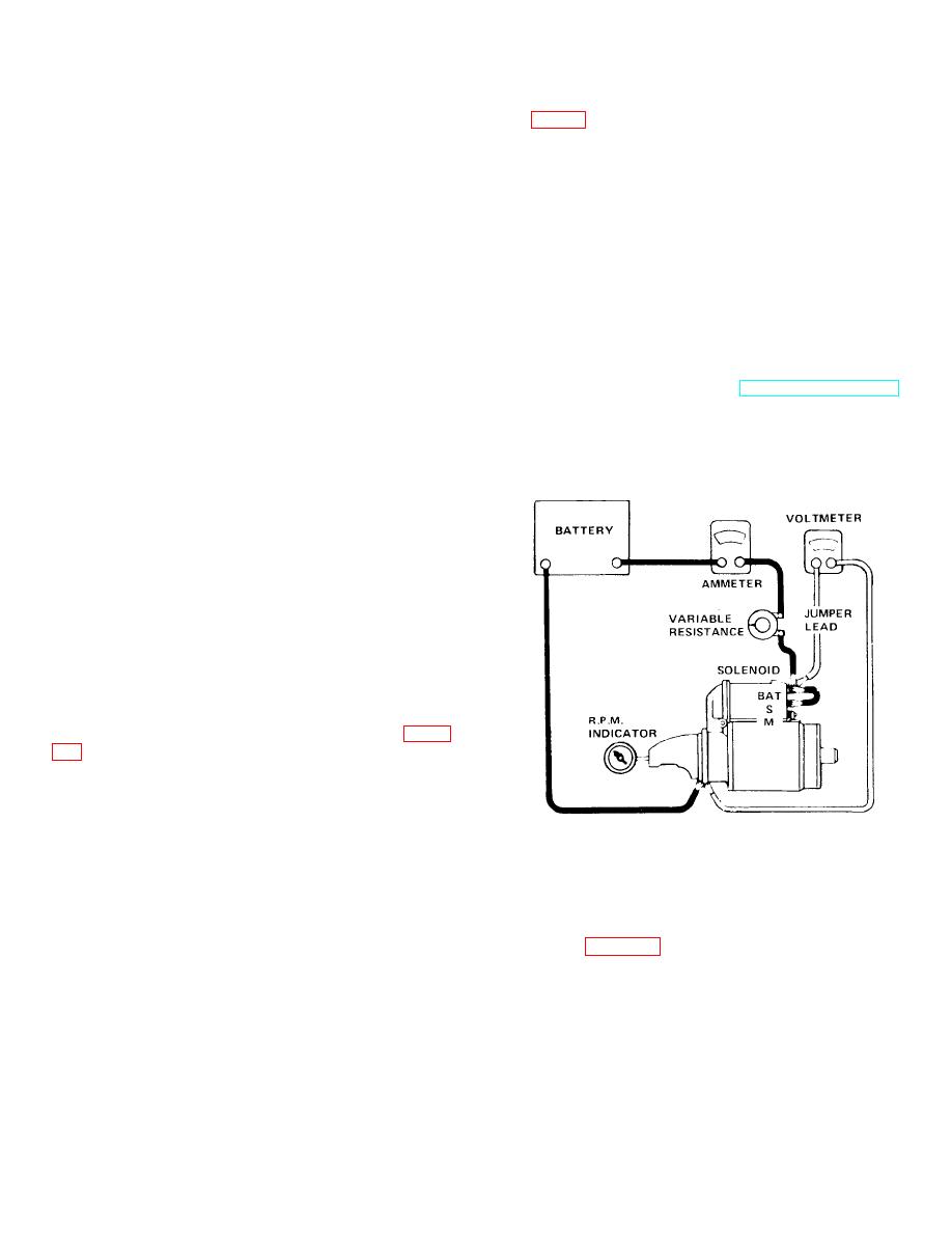
(1) Connect the starter in series with an
ammeter capable of reading several hundred amperes,
a variable resistance and a voltmeter as shown in figure
(2) Operate starter and adjust resistance
to obtain a reading of 9 volts on voltmeter.
(3) Check rpm of starter. The starter must
operate at 5,500 to 10,500 rpm.
TA067404
(4) With starter operating at specified
Figure 4-7. Starter no-load test.
rpm, check ammeter. Reading must be between 50 to
80 amps.
c.
Resistance Test.
(5) If starter operates at lower speed and
(1) Connect starter into a circuit with an
with a high current draw, repair starter.
ammeter, voltmeter, variable resistance and a battery
(6) If starter does not operate within limits
as shown in figure 4-8.
specified in (3) and (4) above, repair starter.
4-5
|
|
Privacy Statement - Press Release - Copyright Information. - Contact Us |
