 |
|||
|
|
|||
|
Page Title:
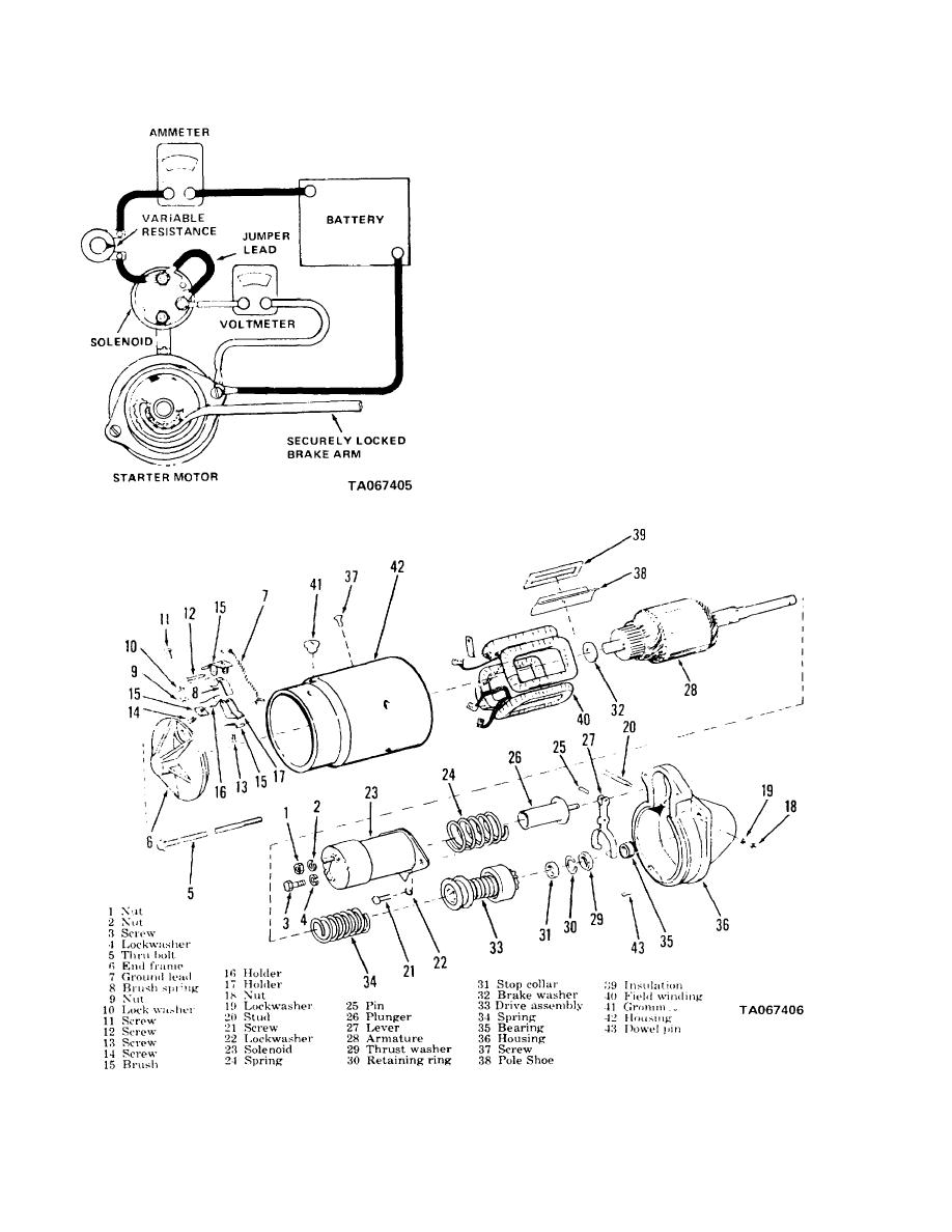
Figure 4-9. Starter, disassembly and reassembly. |
|
||
| ||||||||||
|
|
 TM 10-3930-630-34
(2) Securely lock the pinion, using the
brake arm, to prevent the armature from turning.
(3) Energize the starter with 4 to 5 volts.
Adjust voltage with variable resistance.
(4) Current reading must be from 270 to
310 amps. If current is not within limits specified, repair
starter.
d. Disassembly. Disassemble the starter
assembly in numerical sequence as illustrated in figure
Figure 4-8. Starter resistance test.
Figure 4-9. Starter, disassembly and reassembly.
4-6
|
|
Privacy Statement - Press Release - Copyright Information. - Contact Us |
