 |
|||
|
|
|||
|
Page Title:
Section IV. REMOVAL AND INSTALLATION OF MAJOR COMPONENTS |
|
||
| ||||||||||
|
|
 g. Part Replacement. Replace authorized parts
f. Welding Repair. Welding must be performed
w h i c h a r e w o r n o r d e f e c t i v e w i t h n e w parts.
by a qualified welder. Welds must provide complete
Consider such factors as age, mileage, operating
fusion and penetration and comply with governing
hours, usage, and parts availability to determine
specifications. I n s p e c t a l l w e l d s u s i n g a
the necessity of part replacement.
radiographic or magnetic particle process. Grind all
new welds flat and smooth whenever possible.
Section IV. REMOVAL AND INSTALLATION OF MAJOR COMPONENTS
2-8. Engine
a. Removal.
Note. It is recommended that the engine and transmission
be removed as a unit. Clean the engine and transmission before
removing from the truck.
(1) Remove the counterweight. Refer to TM
10-3930-624-12.
Note. Tag all hydraulic lines, coolant lines, electrical
wiring, fuel lines, and mechanical linkages which are
disconnected for engine removal. This will ensure proper
reinstallation of the engine.
(2) Drain the engine cooling system and
disconnect the coolant hoses from the radiator.
(3) Refer to TM 10-3930-624-12 and drain
the oil from the transmission. Disconnect the
transmission oil cooler lines at the radiator. Cap or
plug openings.
(4) Refer to TM 10-3930-624-12 and remove
the radiator from the truck.
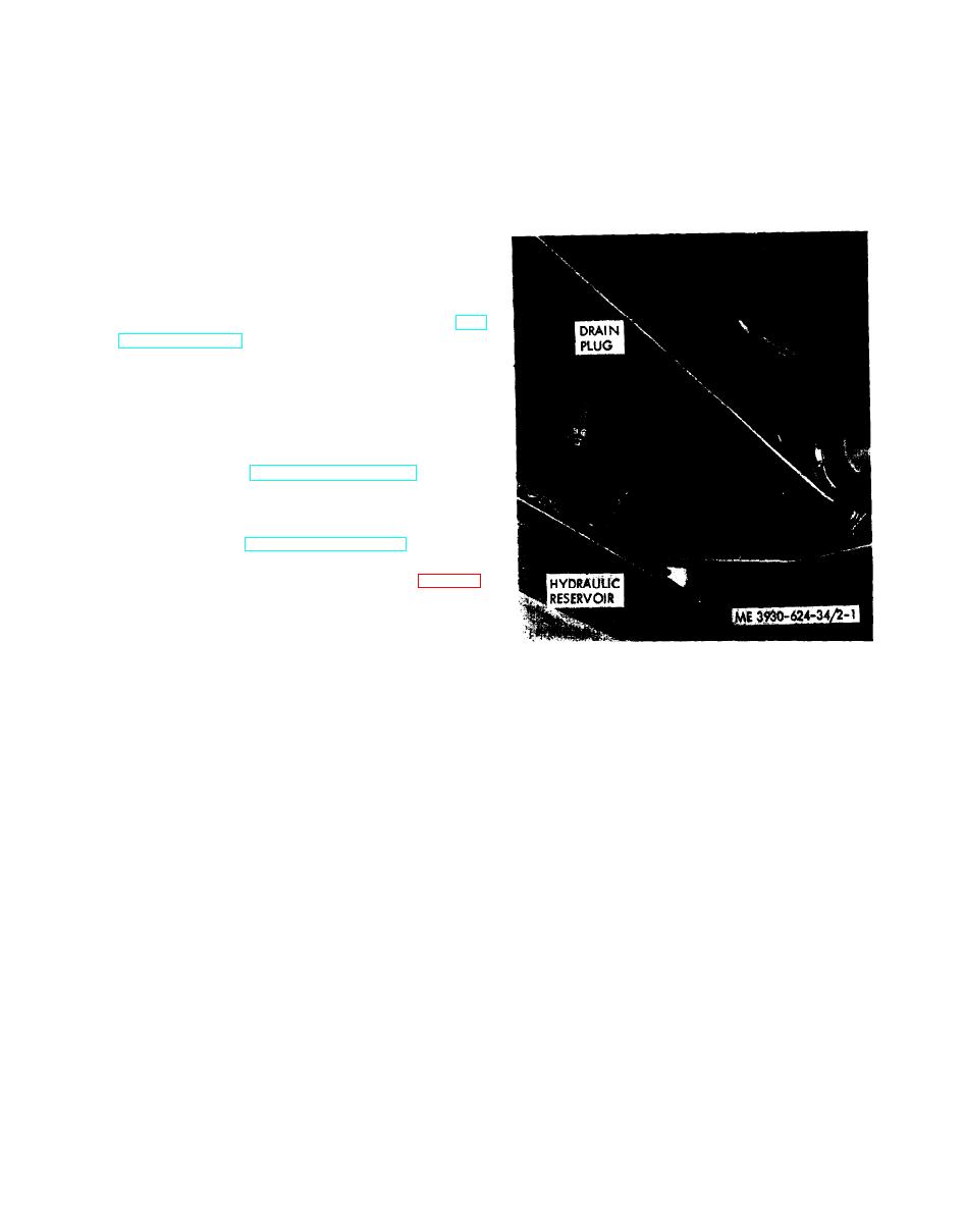
(5) Drain the hydraulic reservoir (fig. 2-1).
Disconnect the hydraulic hoses at the pump (fig. 2-
2). Cap the ends of the hoses and the pump inlet
and outlet ports to prevent the entry of foreign
material. Remove the hose clamps on each side of
the oil pan. Tie the lines out of the way.
Figure 2-l. Hydraulic reservoir drain.
2-7
|
|
Privacy Statement - Press Release - Copyright Information. - Contact Us |
