 |
|||
|
|
|||
|
|
|||
| ||||||||||
|
|
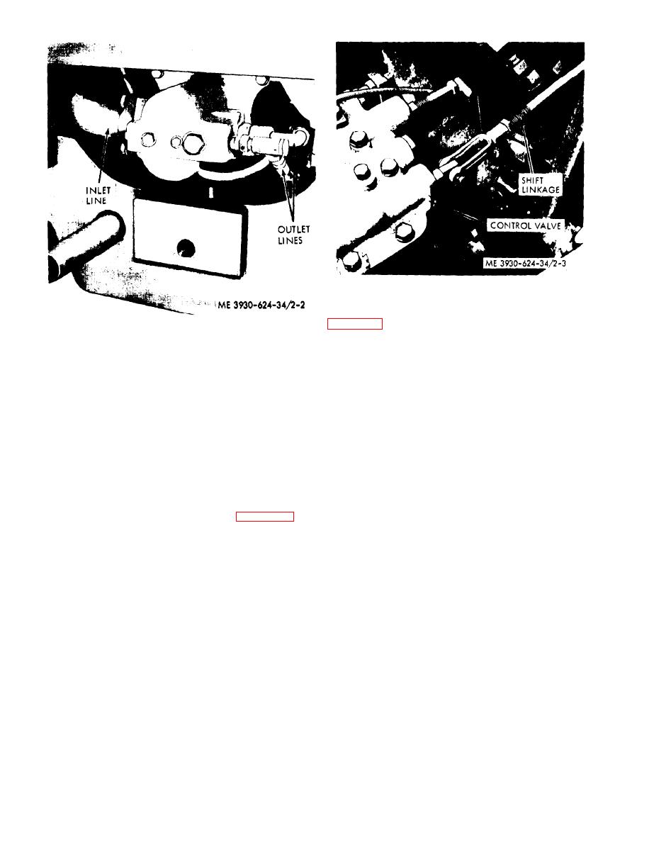 Figure 2-3. Shift linkage.
(13) Disconnect the throttle linkage. Refer to
Figure 2-2. Hydraulic liner.
(6) Remove the toe plate and floor plate.
(7) Remove the hood assembly, hood support
and side panels.
(8) Remove the seat and seat support.
(9) Remove the front grille.
(10) Disconnect the battery leads at the
battery. Remove the battery and battery case.
Remove the wiring harness.
(11) Close the fuel shutoff valve. Disconnect
the fuel line at the inlet side of the fuel pump. Cap
openings.
(12) Disconnect the shift linkage at the
transmission control valve. Refer to figure 2-3.
2-8
|
|
Privacy Statement - Press Release - Copyright Information. - Contact Us |
