 |
|||
|
|
|||
|
Page Title:
Section VIII. MAINTENANCE OF THE FUEL SYSTEM |
|
||
| ||||||||||
|
|
 Connect the fuel inlet line (6, fig. 4-7), governor control
rod, choke control cable, and accelerator rod.
(4) Connect the exhaust pipe to the exhaust
manifold flange, and install the carburetor air cleaner
hose.
(5) Install the air cleaner, seat and seat deck, and
side panels. Open the fuel shut-off valve at the fuel
tank.
Figure 4-6. Manifold mounting
Section VIII. MAINTENANCE OF THE FUEL SYSTEM
4-19.
Carburetor
a.Adjustment. (fig. 4-7.)
Note. Before making any adjustments. Warm the
engine up to normal operating temperature.
(1) General. Proper mixture of fuel and air is
controlled by a fixed jet and an adjustable idle fuel jet
14).The throttle stop screw (2) is preset to maintain the
correct engine idle speed. Adjustments are properly set
during manufacture.
(2) Throttle stop screw adjustment.
(a) Turn the throttle stop screw (2) in
against the stop to hold the throttle slightly open (fig. 4-
(b) After idle fuel adjustment is made,
adjust the stop screw to obtain an idle speed between
500 and 550 rpm.
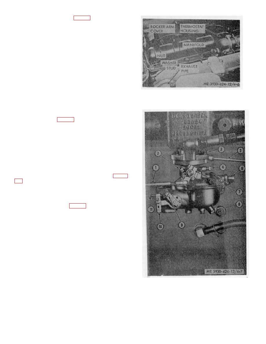
KEY to Fig. 4-7:
1.
Accelerator rod
2.
Throttle stop screw
3.
Nuts and lockwashers
4.
Idle adjusting jet
5
Governor control rod
6.
Fuel inlet line
7.
Throttle lever
8.
Bowl drain plug
9.
Swivel connection
10.
Choke control bracket
11.
Choke control cable
Figure 4-7. Carburetor adjustment.
4-14
|
|
Privacy Statement - Press Release - Copyright Information. - Contact Us |
