 |
|||
|
|
|||
|
Page Title:
INSTALLING PISTON AND ROD-ASSEMBLIES . |
|
||
| ||||||||||
|
|
 TM 10-3930-623-34
NOTE
NOTE
Some piston rings have a taper face.
Mate indicator dimple on camshaft
These rings are clearly marked TOP
gear with those on crankshaft gear to
on upper side. Install with this side
insure correct timing of valves to
up.
piston operation.
6-23. INSTALLING PISTON AND ROD-ASSEMBLIES .
2. Install key (11) in camshaft keyway. Assemble
Soak piston assembly with rings in OE-30 engine oil,
cam gear (9) to camshaft by driving or pressing it on. At
drain excess oil, and install assembly in cylinder as
the same time hold the camshaft forward with a suitable
follows:
bar through the fuel pump opening in the block so there
is no possibility of the camshaft bumping the expansion
1. Compress rings into ring grooves with a ring
plug at the rear end. This could force it out of position,
compressor. Do not overtighten.
thus causing an oil leak. Check camshaft end play as
2. Place big end of rod into correct cylinder as
shown in figure 7-1, item 11.
indicated by number stamped on rod big end and cap.
3. Install camshaft gear governor drive assembly
Cylinders are numbered from 1 to 6, beginning at the
with balls on camshaft.
timing gear end of the engine. Orient rod big end to
CAUTION
crankshaft journal so it will meet properly. Rods are
Never use camshaft nut to pull gear
properly oriented when offset side of each rod faces
onto camshaft. This will break
away from the adjacent main bearing, and the numbers
threaded end off of a cast iron
stamped on the rod (1 through 6) face the camshaft.
camshaft and damage threads on a
Press piston into cylinder with end of hammer handle.
steel camshaft.
CAUTION
If a rod is installed reversed, the
4. Install camshaft nut (10). Torque nut to 85-90
engine will lock and the rod will
foot pounds.
probably bend on the first attempt to
5. Assemble governor upper race shaft to end of
crank the engine.
camshaft. Lubricate governor with OE-30 engine oil.
3. Lightly oil, then install connecting rod bearing
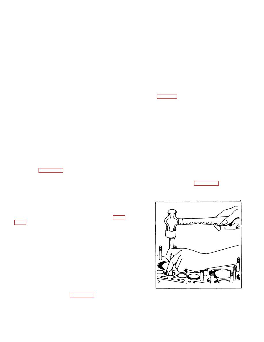
6-26. VALVE GUIDE REPAIRS . Press out excessively
inserts (24, figure 4-28) in connecting rod, position rod
worn or damaged valve guides with arbor press or
on crankshaft secure bearing cap in place. Torque nuts
suitable driver from cylinder head side (see figure 64).
(22) to 40-45 foot pounds, then tighten nuts as
Press new valve guides (4, figure 4-23) into block from
necessary to align slots with cotter pin hole in bolts (21)
top of block. Press until guide is 1-15/32 inch below
and install new cotter pin (19).
cylinder block deck.
4. Turn crankshaft one revolution to be sure
with reassembly.
CAMSHAFT AND CAMSHAFT BEARINGS.
6-24.
Install camshaft bearings (15, 16, 17 and 18, figure
bearing as follows:
1. Align the oil hole in the bearing with the oil
passage in the block which supplies it with lubrication.
2. With a piloted driver, tap each bearing int o
place.
6-25. CAMSHAFT INSTALLATION.
NOTE
When installing camshaft use special
care to prevent camshaft bumping
against and loosening expansion
plug to cause an oil leak.
1. Insert camshaft (19, figure 4-23) into position in
Figure 6-4. Driving Out Valve Guides
block, and install thrust plate (12), washers (14) and
screws (13).
6-5
|
|
Privacy Statement - Press Release - Copyright Information. - Contact Us |
