 |
|||
|
|
|||
|
Page Title:
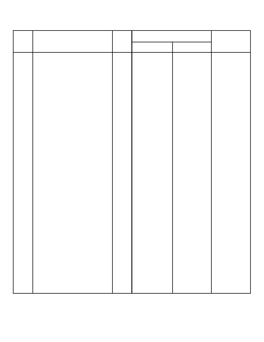
Figure 7-1. Table of Limits and Fits and Points of Measurements (Sheet 1 of 4) |
|
||
| ||||||||||
|
|
 TM 10-3930-623-34
See
Manufacturers'
Ref
Sheet
Specifications
Wear Limits
No.
Point of Measurement
or
Inches
Min-Inches
Max-Inches
Figure
Valve Guide
1
Bore diameter, Exhaust
0.3452
0.3462
0.3477
1
Bore diameter, Intake
0.3432
0.3442
0.3457
2
Top of guide to cylinder deck
1-15/32
1-15/32
Valve Seat
3
Angle
45 deg.
45 deg.
Valve
4
Seat Angle
45 deg.
45 deg.
5
Stern diameter, Exhaust
0.3405
0.3415
0.3385
5
Stem diameter, Intake
0.3405
0.3415
0.3385
Valve Springs
NOTE: Effort in pounds required
to compress spring to length
specified
6
Valve closed, length 1-45/64
47
53
42
Camshaft
Journal diameter
7
Front
1.8715
1.8725
1.8745
8
Intermediate, Front
1.8085
1.8095
1.8115
9
Intermediate, Rear
1.7457
1.7465
1.748S
10
Rear
1.2465
1.2475
1.2495
Bushing inside diameter
Front
1.8745
1.8755
1.8725
Intermediate, Front
1.8115
1.8125
1.8095
Interermdiate, Rear
1.7495
1.7502
1.7475
Rear
1.2495
1.2505
1.2475
Journal to bushing clearance
Front, Intermediate front, rear
0.002
0.004
Intermediate Rear
0.003
0.0045
11
End play
0.005
0.009
Connecting Rod
12
Bearing insert thickness
0.0623
0.0628
0.0618
13
Crank pin diameter
2.0694
2.0601
2.0584
14
Crank pin clearance
0.0008
0.0020
0.0030
15
Side play
0.006
0.010
16
Journal Radii
0.0781
0.01094
Figure 7-1. Table of Limits and Fits and Points of Measurements (Sheet 1 of 4)
Figure
7-1
Sheet
1
Figure
7-1
Sheet
2
7-2
Figure
7-1
Sheet
3
Figure
7-1
Sheet
4
|
|
Privacy Statement - Press Release - Copyright Information. - Contact Us |
