 |
|||
|
|
|||
|
Page Title:
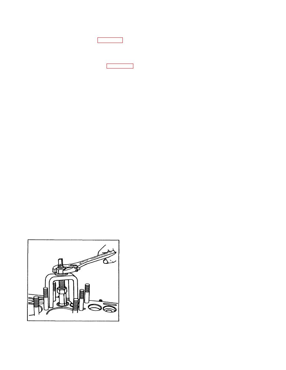
Figure 6-5. Removing Valve Seat Insert With Puller |
|
||
| ||||||||||
|
|
 TM 10-3930-623-34
6-27. EXHAUST VALVE INSERT SEATS. The exhaust
4. Grind valve seat angle with suitable valve seat
valve is mated to a valve seat insert (3, figure 4-23) fitted
grinding tool having a long taper pilot to insure accurate
with an 0.003 to 0.005 inch interference fit to the cylinder
seat to bore. After grinding with pilot still in position, use
block. Replace exhaust valve seats as follows:
a dial indicator to check concentricity of valve seat.
Runout must not be more than 0.002 inch.
1. Use suitable valve seat puller to remove any
loose or defective valve seat, (see figure 6-5).
6-28. INTAKE VALVE SEATS. Grind intake valve seat
Replacement seats are available in 0.010 inch oversize.
in cylinder block the same as the exhaust valve insert
seat. See step 4 above.
NOTE
Always replace valve seat with one
NOTE
0.010 inch more oversize than that
The seat angle for the Continental
removed.
Model F244, Standardized Military
engine is 45 deg for both intake and
2. Use a suitable valve seat counterbore tool to
exhaust valves.
enlarge valve seat bore sufficient to obtain 0.003 to
0.005 inch tight fit (bore less than valve seat outside
6-29. VALVE REPAIRS . Repairs to valves consists
diameter). Counterbore to full depth.
only of refacing the valve face with a suitable valve
grinder tool.
NOTE
Complete counterbore drilling before
1. Grind Continental Model F244, Standardized
starting to reassemble engine to
Military Engine intake and exhaust valves to a 45 deg
prevent chips from falling into
seat angle.
engine.
If the engine is not
completely disassembled, pack valve
2. Check that new contact face concentricity is
chambers with rags to prevent chips
within 0.002 inch with valve stem when checked with a
from falling into oil pan.
dial indicator and "V" blocks. If not, reface.
3. Chill valve seat insert in a container of dry ice for
NOTE
20 minutes. After chilling, position guide in cleaned
If the parallel sides of valve head
counterbore and with suitable driver, tap in position with
(area above seat angle) is reduced to
light hammer. Excessive force may shear sidewall of
less than one-half the original height,
counterbore. Make sure seat is bottomed before it
replace valve.
warms.
6-30. VALVE FACE TO VALVE SEAT CONTACT.
CAUTION
Valves will fail prematurely due to burning, warpage or
Do not touch dry ice with bare hands.
other damage, if the valve to valve seat contact is
It will cause frost-bite due to its
incorrect. Check contact as follows:
extreme low temperature.
1. Lightly coat valve seat with Prussian blue.
Assemble valve to cylinder block and rotate slightly to
obtain "pattern". Remove valve.
2. Transferred blue line on valve shall be between
1/16 and 3/32 inch wide and positioned so at least 1/64
inch is clear on both sides. If blue runs off either or both
sides correct as follows:
a. Head side. Regrind valve seat with a 15
deg stone to reduce seat face diameter.
b. Stem side. Regrind valve seat with a 60
deg to 75 deg stone to increase inner seat diameter.
Figure 6-5. Removing Valve Seat Insert With Puller
6-6
|
|
Privacy Statement - Press Release - Copyright Information. - Contact Us |
